IMPORTANT - INCORRECT INSTALLATION WILL INVALIDATE WARRANTY
PW-SMB2000 ‘ |

Y O U R I N S T A L L A T I O N I N S T R U C T I O N S
SMARTBOOST - RB
READ ME
This is a high performance, high specification pump and has precise installation requirements.
This booklet provides an overview of the supplied products and is not a substitute for the complete installation instructions supplied with each component. Please pass all manuals on to the householder after installation.
It is necessary to retain proof of purchase in order to facilitate any warranty claim.
Ensure pump has its own or a very good power supply
with recommended 30 mA RCD and suitable type B circuit breaker
QUALIFIED PLUMBER & ELECTRICIAN TO CARRY OUT INSTALLATION
Updated December 2022
WARRANTY
One year from date of purchase (parts and labour) with a second year activated (parts only) on return of the Extended Warranty Form.
Proof of purchase will be required. Note : any labour costs, other than Pump World, will only be covered by prior agreement.
BOX CONTENTS INSTALLATION KIT
Smartboost-RB x1 Stainless Steel Flexible 1.0” x2 Y Strainer 1.0” x1
Vessel Kit x1 Lever Ball Valve 1.0” x2 Brass Nipple x1
Acoustic Mat x1 Reducing Bush (if applicable) x1
PUMP PERFORMANCE
MODEL KW AMPS DIMENSIONS (MM) MAX PRESSURE MAX FLOW RATE
SMARTBOOST 4 - RB 0.50 3.3 L380 x W240 x H880 4.6 BAR 70 LPM
SMARTBOOST 5 - RB 0.75 4.5 L390 x W240 x H880 5.8 BAR 70 LPM
SMARTBOOST 6 - RB 1.10 5.6 L410 x W240 x H880 6.0 BAR 120 LPM
RECOMMENDED MINIMUM TANK SIZE : 455 LITRE
These pumps are often used to boost the pressure (from a break tank) whilst maintaining a constant pressure during changes in demand. Please seek technical help on 01793 820142 for further information.
KEY POINTS BEFORE PROCEEDING
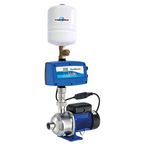
This set consists of a pump, smart inverter and electronic pressure transmitter (also known as the pressure sensor), 5 way connection, vessel and pressure gauge. Always disconnect the inverter from the power supply before carrying out operations on the system’s electrical or mechanical components. After disconnecting from the power source, wait at least 4 minutes before carrying out any work to allow the capacitor in the internal circuit to discharge.
When pumping water from a break tank it is necessary to install a float switch to protect the pump from running dry.
To complete the system, flexible hoses and shut off valves on suction and delivery should be installed.
To not do so may invalidate warranty.
Electrical Supply Ensure pump has its own or a very good power supply with recommended 30 mA RCD and suitable
type B circuit breaker.
Water Temperature If pumping, the hot water maximum temperature is 60°C.
Pump Installation The expansion vessel pressure must be set at 0.5 Bar below the pump set point. The vessel must be inflated and
checked when the system and pump is not pressurised. The pump must be adequately ventilated.
Installation Kit Flexibles : Do not bend more than 10 degrees.
Lever Ball Valves : Additional valves should be installed before and after pump to facilitate maintenance.
A ¾” Equilibrium Ball Valve will improve refill of cold storage tank (not supplied).
Jointing compound must not be used in the supply pipework of the pump.
Required By Law All wiring complies with British standards and is fused and earthed (use a 13 amp fuse in spur or plug).
This pump complies with the United Kingdom Water Fitting Byelaws Scheme and must be fitted by a
competent installer in accordance with Water Byelaws and the requirements of the Institute of Electrical Engineers.
Please refer to the individual component manuals for complete installation instructions.
EQUIPMENT LAYOUT
We can supply all components listed below, call for specification on 01793 820142
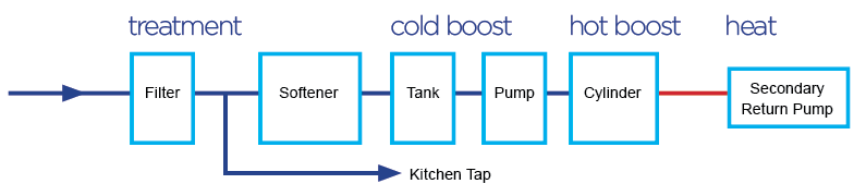
Filter
Water filters improve the taste and quality of your drinking water.
Kitchen Tap
The kitchen tap should be drawn off after the filter and before the rest of the equipment.
Softener
Water softeners collect hard water salts from your water that form limescale - preventing staining and watermarks on sanitary ware and calcium build-up on heating elements, pumps, tanks and vessels.
Tank
Cold water storage to meet demand when required.
Pump
Provides boosted pressure and flow.
Cylinder
Hot water storage to meet demand when required.
Secondary Return Pump
Circulates hot water to provide instant hot water at the taps.
TYPICAL LAYOUTS
SINGLE PUMP LAYOUT

A bypass system, with isolating valve, is recommended to cover loss of pump operation.
TWO PUMP LAYOUT (WITH DUTY ASSIST) FOR UNVENTED SYSTEMS

Note : where a bypass system is installed, it will be necessary to fit a double non-return valve.
BOOSTING GRAVITY OR VENTED SYSTEMS IS NOT RECOMMENDED
QUICK START GUIDE
Pump must be adequately ventilated.
- Plumb and prime the pump (see pump manual supplied for instruction). Ensure pump has its own or a very good power supply with recommended 30 mA RCD and suitable type C circuit breaker.
- Press Menu and check the nominal motor current (amp rating) of the pump. See Page 1, ‘Pump Performance’ table for correct rating for your pump model. You can also confirm this on the pump label. This is set under ‘A’. Use the up down arrows to set, press ENTER to save and go to the next parameter.
The picture below is for illustrative purposes only - refer to your pump for correct motor current.

- Scroll to EL. If a float control is fitted, change setting to 1. Press ENTER to save and go to next parameter.
- Scroll to SP. The pump will be set at 3.5 Bar as standard. You are able to adjust the running
pressure by using the arrows. Press ENTER to save and go to next parameter.
- Scroll to NP. This is defaulted to 0, when the pump runs out of water it will stop.
- Press Set to finish.
There is a Youtube video from the factory showcasing the set up of the controller. Please search Lowara Resiboost and watch the video on the Lowara - A Xylem Brand official youtube channel.
For the full instructions, please use the individual component manuals supplied.
NOISE
These are quiet pumps and the following recommendations are made to minimise any extraneous noises.
- Pump should be placed on the acoustic mat provided to help absorb vibration.
- Pump must not be screwed or bolted to the floor.
- Pump is recommended for placing on a paving slab or concrete floor.
- Ensure that all pipework is firmly secured and not in contact with any stud walls.
RB INVERTER DRIVE CONTROLLER
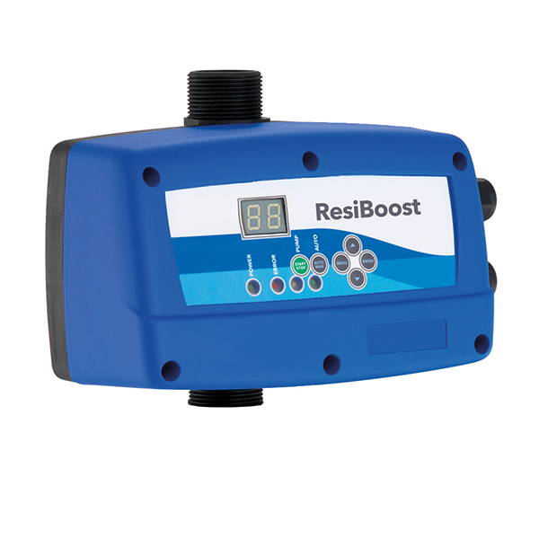
Application : Allows a constant set pressure regardless of demand for maximum comfort.
This variable frequency drive is specially designed for maintaining constant pressure independent of flow.
Energy savings are the result of the precise speed control. It turns a fixed speed pump into a variable speed pump.
Easy to set up and operate, just select the required pressure 'plug and play' using the control and panel with LCD display. Built-in dry run protection and pressure transducer with digital indicator. Stored information of operated hours, number of starts, connections to the power supply, register of alarms. Built in protection of over current, incorrect supply voltage and short circuit. Anti-icing protection.
Compact design with top quality components that guarantee high reliability and a trouble-free life. The inverter has in-built protection against various system and electrical faults. Smooth operation and soft starting ensure silent running and an extended pump life.
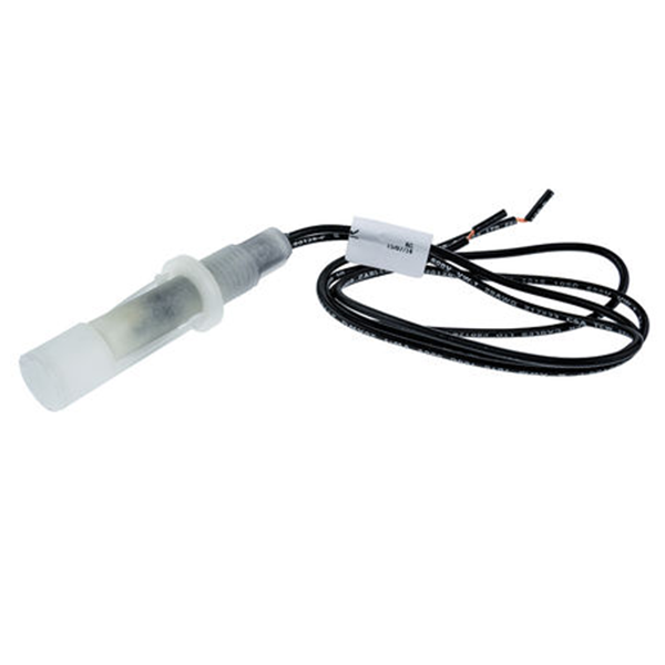
FLOAT SWITCH OPTIONS (IF APPLICABLE) | |
* USE J102 FOR WIRING * | |
DOUBLE PROTECTION FLOAT Suitable for clean and dirty water. The microswitch assembly inside the float, axially mounted inline with the weight, changes contacts according to the float’s position. Therefore, as the liquid level drops or rises slowly, a pump or flow control suitably connected can be switched in or out to maintain an average level of the liquid. By connecting only one side of the switch, the unit can also be used to fill or empty the tank as required. Float Housing : Non-toxic, corrosion resistant polypropylene. Cable : PVC 3x1, 10.0 m Equipment rated to 50°C. Protection Degree IP68. Use the brown and black wires for low level water protection. The wire that is not used must be correctly insulated. Use J102 on the pump set for wiring. Follow instructions supplied with float switch for full details. | |
RIGID ARM FLOAT SWITCH WRAS Approved Horizontal mounting float level switch constructed from polypropylene. Consists of reed switch and pivoted actuator magnet. If the cold water tank is undersized, or there is poor mains pressure resulting in poor water recovery, the low level water protection will prevent the pump from running when the water level gets too low in the cold water tank. Use volt free connections. Do not put 230V power on to terminals. | |
If you would like to order a Float Switch, please call the sales team on 01793 820142. | |

LEAK DETECTION KIT
(if applicable)
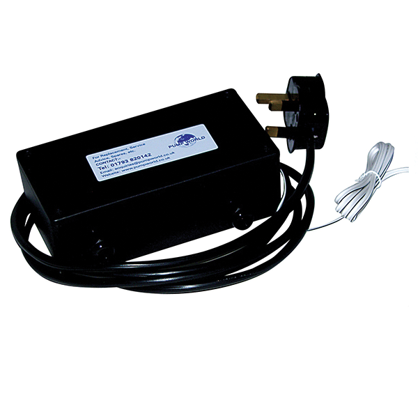
Application : Complete water detection system.
Leak detectors that operate through a water sensitive cable which sounds an alarm and cut the power supply to the pump if a leak is detected.
Supplied with pump sensor cable, alarm and relay. If the sensor cable detects water anywhere along its length, an alarm relay operates to signal that water has been detected, and power to the pump will be shut off. As soon as the leak is fixed and the cable has dried out, the system resets itself. The only requirement is that the water actually touches the sensor cable, high humidity will not cause an alarm unless condensation starts to form.
The leak detectors will detect very small quantities of water, less than 5 ml (one teaspoonful) will trigger an alarm. Response is fast, typically a few seconds.
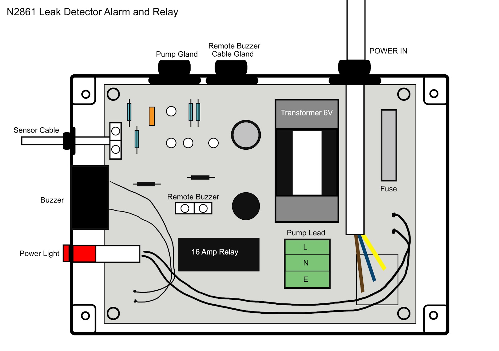
INSTALLATION
The pump should be mounted horizontally in the centre of a suitable tray with the sensor cable near to, but not touching, the pump. It is advisable to place small weight (not metal) over the cable to keep it flat.
We would recommend fitting an overflow to the tray to allow excess water to drain to the waste.
1. Remove the four screws holding the terminal lid cover and wire the pump power lead into the connector block provided (terminals marked ‘Live’, ‘Neutral’ and ‘Earth’). This is located in the green socket on circuit board.
2. Remote alarms can be installed using the volt free connector block also provided.
3. Replace the terminal lid and the four screws.
4. Please note once the alarm has been activated, the pump will not work again until the sensor cable is dry.
If you would like to order the Leak Detection Kit, please call the sales team on 01793 820142.
SMARTBOOST - RB EXTENDED WARRANTY FORM
Fill in this form, make a copy and email / post (the copy only) back to us. It is also available to fill in online.
WARRANTY
One year from date of purchase with a second year activated (pump only) on return of the Extended Warranty Form.
Proof of purchase will be required. Note : any labour costs will only be covered by prior agreement.
Please complete the form, scan or photograph, and email it to enquiries@pumpworld.co.uk
You can post a copy of the form to : Pump World, Unit 11 Woodside Road, South Marston Industrial Estate, Swindon, SN3 4WA
You can fill the form in online via our website - Service > Extended Warranty > Super / Smart Pumps.
Pump World Ltd © All Rights Reserved. Unit 11 Woodside Road South Marston Business Park, Swindon, Wiltshire, SN3 4WA
Tel: 01793 820142 Email : enquiries@pumpworld.co.uk Website : www.pumpworld.co.uk