
Edge Bevel Decals
Version - 2.1.0
Document Last Updated - 04 January 2023
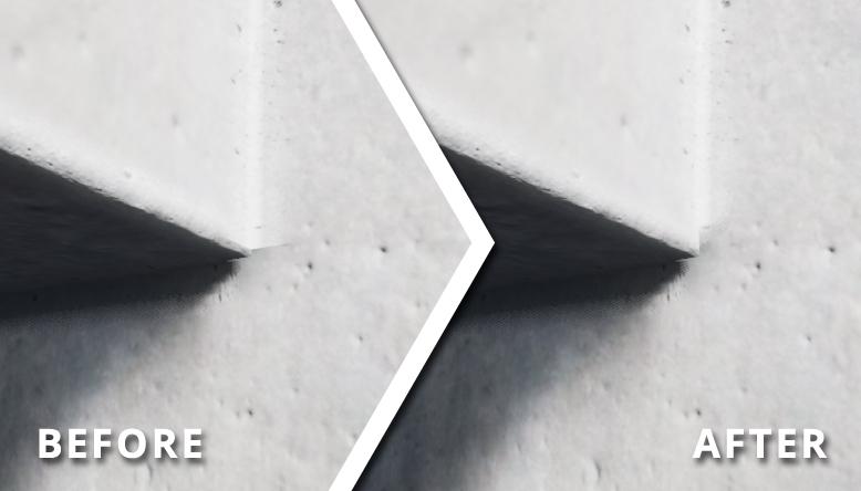
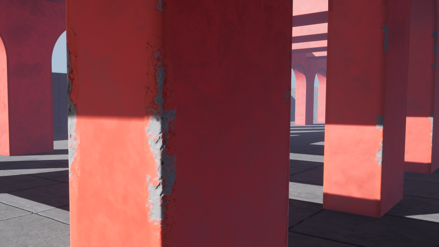
The Edge Bevel Decals package allows environment artists to apply specially designed decals to mesh edges and give them a beveled appearance. They add a considerable amount of detail to BSP brushes, urban environments, and interiors built using modular meshes.
The blueprint makes use of an editable spline to determine the length and shape of the decal element when matching it up with the mesh or brush in question. You can change the base color, detail textures, and normal maps so that the beveled edges match your assets' look. The material makes it possible to paint cracks on every decal component using the editor's vertex painting tool. You can modify the color, tiling, and texture values of the painted damage to refine the look further. If you want to reduce draw calls, the editor's built-in merge tool will allow you to combine the placed decals into a single mesh.
The support of the Edge Bevel Decals is currently limited to rectilinear (90°) edges.
Table of Contents
How to use the Edge Bevel Decal
Additional Version 2 Parameters
Version 1.0.0 - 27th January 2021
Version 2.0.0 - 27th September 2021
Version 2.1.0 - 4th January 2023
Important Information

Figure 1.
Figure 2.
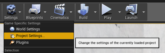
Figure 3.
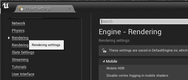
Figure 4.
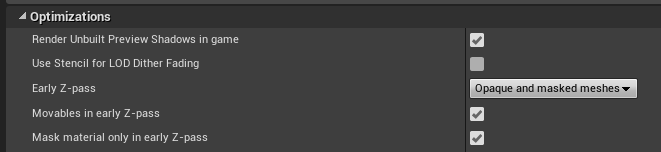
- The decal makes use of a dithered transparency mask. This technique enables the decal to work efficiently in both stationary and static lightmap environments. To use an optimized version of the dithered transparency mask, you’ll have to enable the early z-pass functionality (Figure 1). Open up “Project Setting” (Figure 2) and then go to “Rendering Settings” under the “Engine” section (Figure 3). Scroll down until you find the “Optimizations” tab (Figure 4). Click on the “Early Z-pass” drop-down and select “Opaque and masked meshes”. You also have to enable the “Mask material only in early Z-pass” checkbox. You may need to restart the engine to enable this feature.
Figure 5.
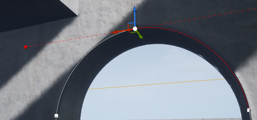
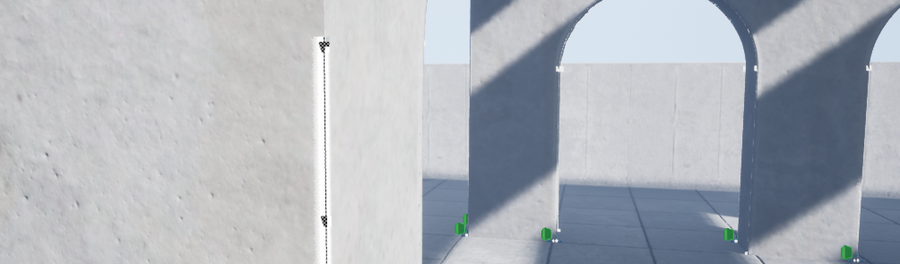
- You can manipulate the Edge Bevel Decals using the built-in spline component (Figure 5). Each control point allows the decal to be adjusted to fit the length, shape, or profile of the edge that you want to improve. You can, for example, use the decal on arches. Due to UE4 splines’ inherent limitations, you can only bend and twist the splines within tolerable thresholds. You have to experiment with the spline component to determine how far you can push it. If the spline component breaks, you can always duplicate or add a new decal blueprint at the point where the spline breaks.
Figure 6.
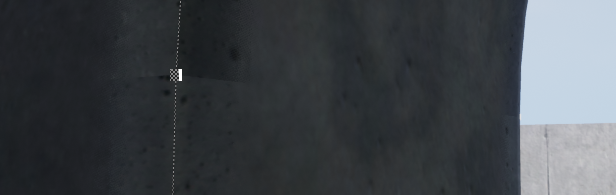
Figure 7.
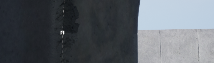
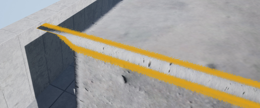
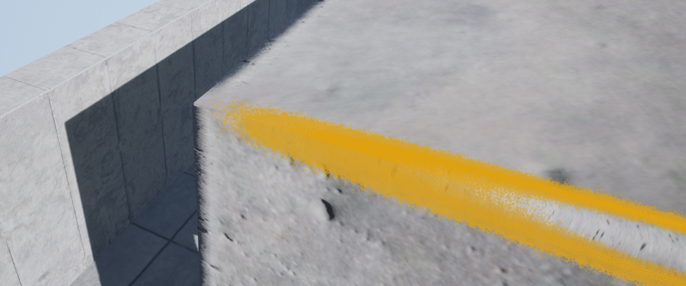
- The blueprint stretches a single decal mesh between two control points. As soon as you add a new control point between two existing points, two new meshes will replace the single mesh, respectively. Keep this in mind when using static lighting as a seam will appear where the two meshes split (Figure 6). Painting some damage over a seam can remedy the issue somewhat (Figure 7). The documentation covers the painting of damage using the vertex painting tool later on in this document.
Figure 8.
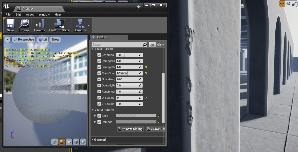
- You can independently edit several parameters on every copy of the blueprint in your scene (Figure 8).
Figure 9.
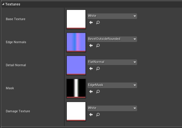
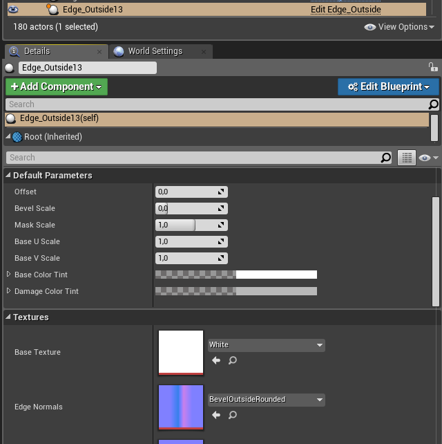
- Under “Textures”, you will find five editable texture slots (Figure 9). The “Base Texture” slot will enable you to add a tileable detail texture that you can use to blend the decal with the underlying mesh. The “Edge Normals” slot contains the normal map that provides the edge with its distinct beveled look. The package includes a rounded and flat bevel texture variant for both inside and outside edges. The “Detail Normal” slot allows you to add a normal map that tiles with the texture in the “Base Texture” slot. The “Mask” texture slot contains a texture that adds a dithered opacity effect to the bevel’s edges. The “Damage Texture” slot contains the albedo texture that blends with the damage you paint when using the vertex paint tool.
How to use the Edge Bevel Decal
Place the Decal
Figure 10.
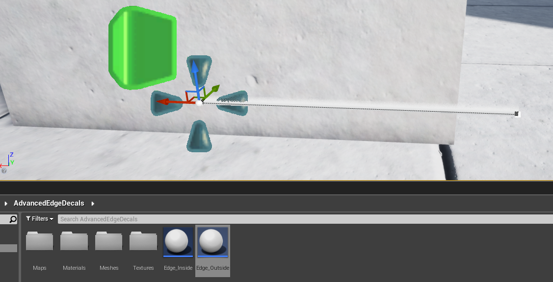
- Drag the “EBD_InnerEdge” or “EBD_OuterEdge” into the scene, depending on the type of edge (Figure 10).
Figure 11.
- Rotate the blueprint to fit the edge in question (Figure 11).
Figure 12.
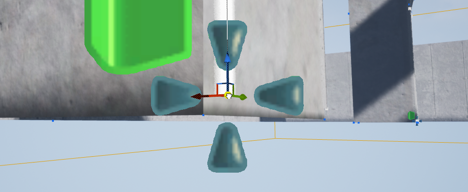
Figure 13.
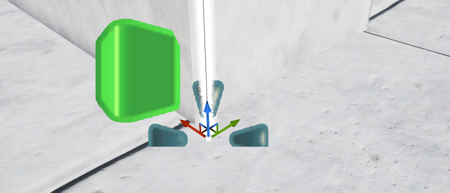
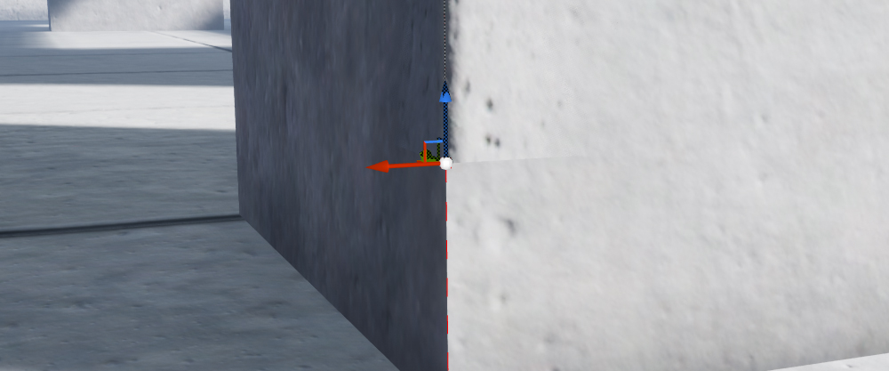
- To get the best result, you need to position the blueprint’s origin as close to one of the edge’s vertices as possible. You can use the editor’s built-in vertex snapping tool to snap the blueprint to that vertex. Press and hold the “v” key, then click-and-hold the sphere at the center of the blueprint’s translation widget (Figure 12). The nearest vertices on the mesh will appear by holding this key combination, which will enable you to drag and snap the blueprint to the required vertex (Figure 13). If you struggle to snap it to the vertex, reposition the camera until you are successful. You will find more information about vertex snapping in UE4’s official documentation.
Figure 14.
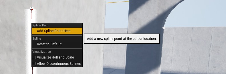
Figure 15.
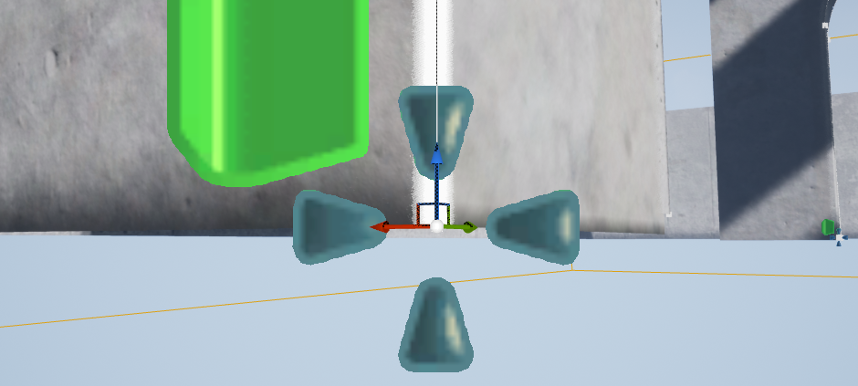
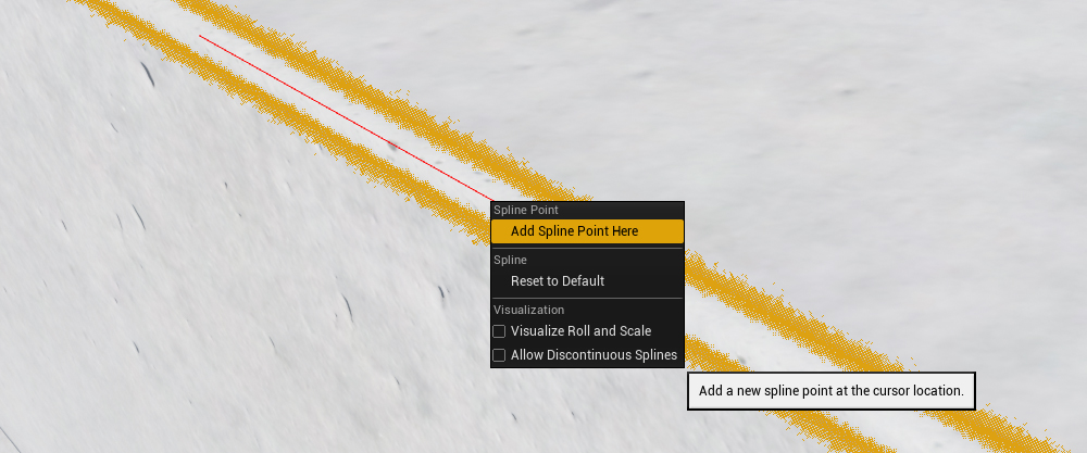
- To add a control point, right-click on the blueprint spline at any point between the two existing control points. When the drop-down menu appears, click on “Add Spline Point Here” to add a new spline point controller at that point (Figure 14). You can also extend the spline with additional control points in another way. Click on the last control point on your spline. Hold the “Alt” key and drag out a new control point (Figure 15).
Fix Z-Fighting
Figure 16.
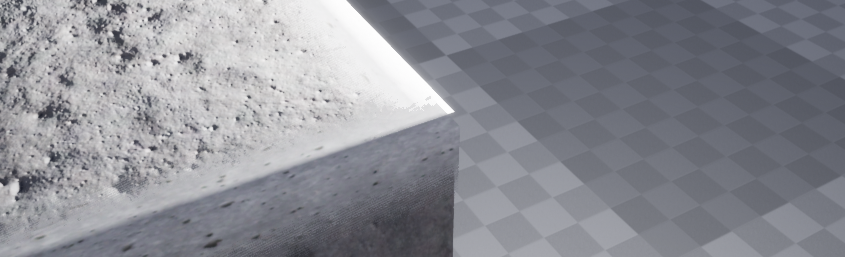
Figure 17.
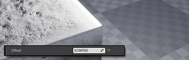
You may encounter a z-fighting issue when two Edge Bevel Decals intersect
(Figure 16). Use the "Offset" spinner to push the decal out from the point of origin and eliminate the problem (Figure 17).
Change Parameters
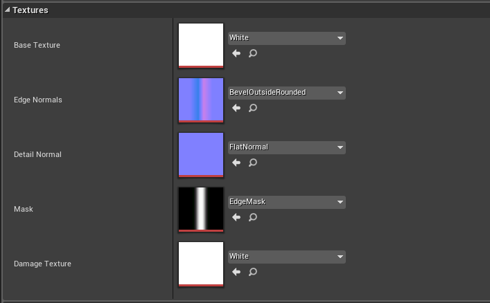
Figure 18.
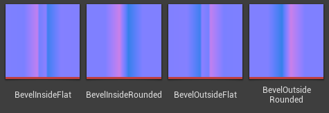
Figure 19.
- You can add custom textures to the “Base Texture”, “Edge Normals”, “Detail Normal”, “Base Texture”, “Mask”, and “Grout Texture” slots (Figure 18). The package contains four beveled normal map textures for your convenience (Figure 19).
Figure 20.
- You can paint damage on the decal using the editor's built-in vertex painting tool (Figure 20).
Figure 21.
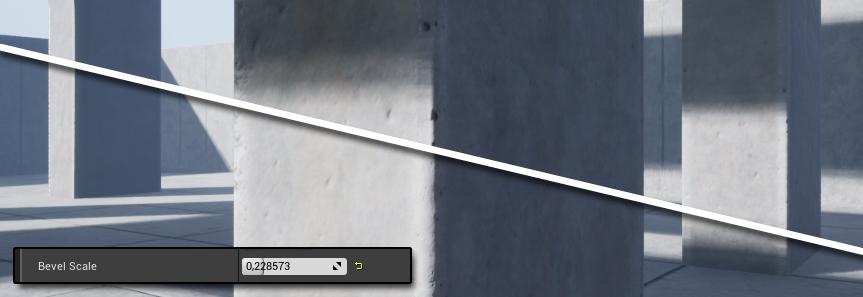
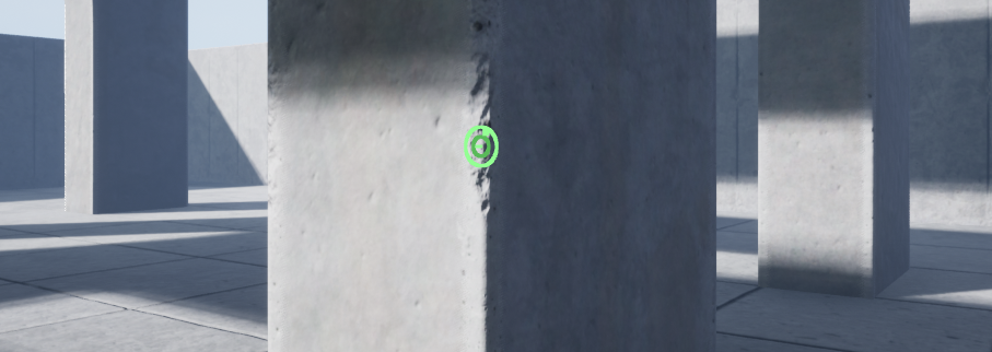
- You can adjust the size of the bevel using the “Bevel Scale” spinner (Figure 21).
Figure 22.
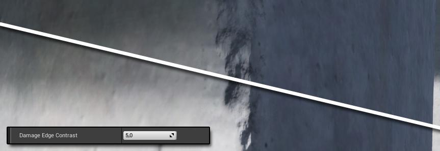
- You can use the “Damage Edge Contrast” spinner to adjust the edge contrast of any damaged areas painted using the vertex paint tool (Figure 22).
Figure 23.
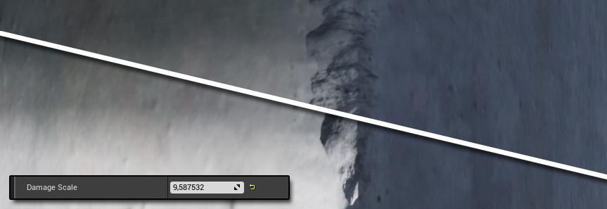
- You can use the “Damage Scale” spinner to adjust the tiling of the painted damage
(Figure 23).
Figure 24.
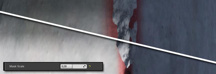
Figure 25.

- The “Mask Scale” spinner adjusts the size of the dithered transparency mask
(Figure 24). This value needs to be used in conjunction with the “Bevel Scale” spinner to achieve the desired look. The mask is handy when using the decal to hide low-polygon curvatures (Figure 25).
Figure 26.
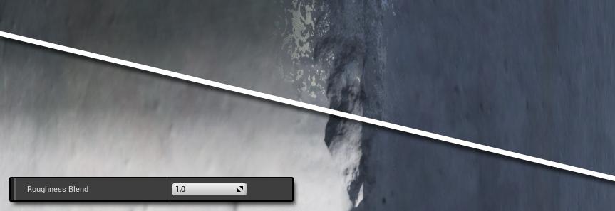
- The “Roughness Blend” spinner value takes the red channel of the “Base Texture” input and blends it with the “Overall Roughness” spinner value
(Figure 26).
Figure 27.

- The “Base U Scale” tiles the “Base Texture”, “Base Normal”, and the “Damage Texture” on the U axis of those textures (Figure 27).
Figure 28.

- The “Base V Scale” tiles the “Base Texture”, “Base Normal”, and the “Damage Texture” on the V axis of those textures (Figure 28).
Figure 29.
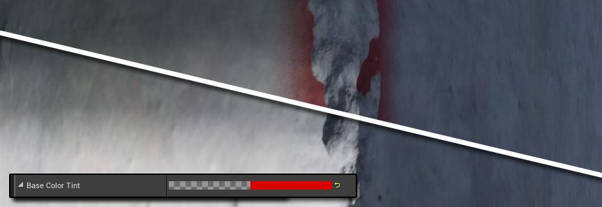
- The “Base Color Tint” determines the edge decal’s hue and is blended with the “Base Texture” (Figure 29).
Figure 30.
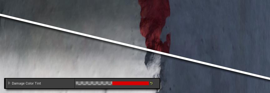
- The “Damage Color Tint” determines the tint of the damage painted using the vertex paint tool and blends with the “Damage Texture” (Figure 30).
Figure 31.
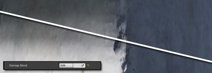
- The “Damage Blend” spinner determines the prominence of the damage painted with the vertex tool (Figure 31).
Figure 32.

- The “Overall Roughness” spinner determines the decal’s overall roughness independent of the “Base Texture” used (Figure 32). The resultant value of the “Overall Roughness” spinner blends with the value of the “Roughness Blend” spinner. This parameter is useful when the roughness derived from the base texture does not suit the mesh roughness underneath.
Figure 33.

- The “Mask” slot uses a custom mask texture. For most use cases, you should leave this mask texture as is (Figure 33).
Figure 34.

- You can fill the “Damage Texture” slot with a texture that blends with the damage painted with the vertex paint tool (Figure 34).
Paint Damage
Figure 35.
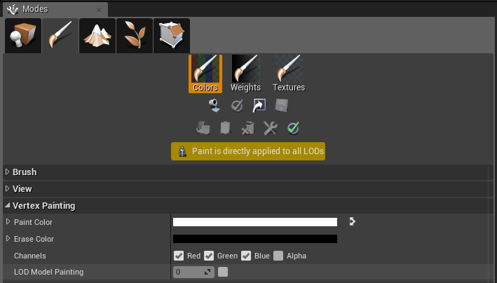
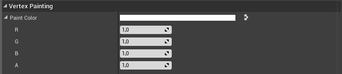
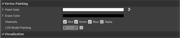
It is relatively easy to paint the damage on a Edge Bevel Decal using the vertex paint tool. Under “Vertex Painting”, make sure the “Vertex Color Painting Mode” is enabled, the “Paint Color” is white, and the “Erase Color” is black (Figure 35).
Figure 36.

To paint damage, hold in the shift key while painting on the edge decal itself. To remove damage, release the shift key and paint over the damaged areas (Figure 36).
Erase parts of the decal
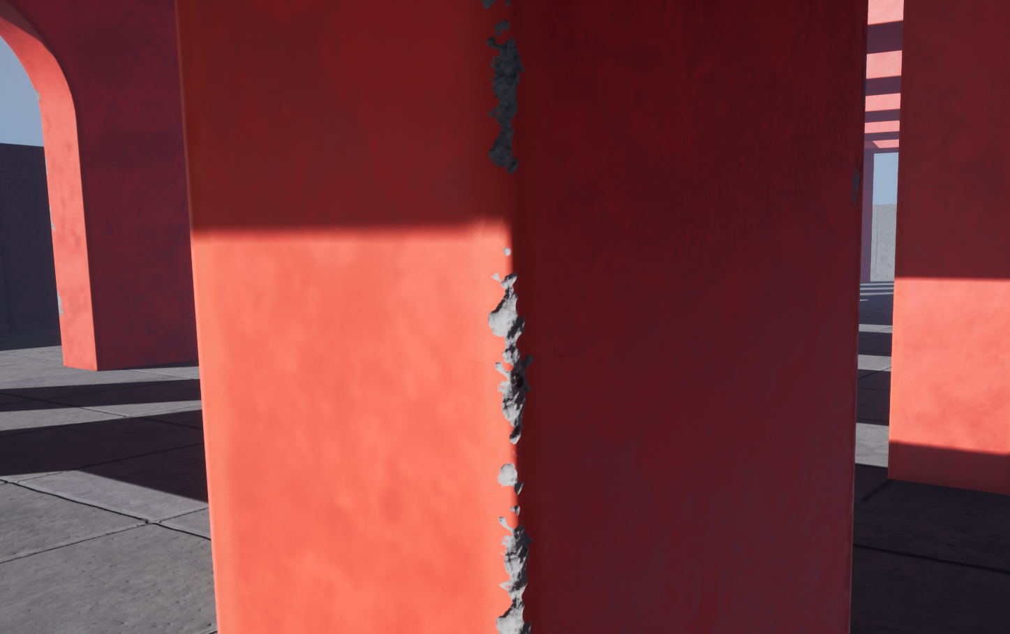
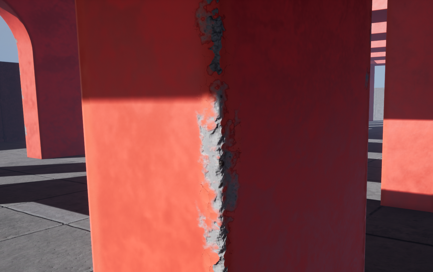
Figure 37.
You can erase parts of the decal using the same vertex painting tool. Having the ability to erase unsightly sections of the decal is especially handy on inner edge bevels
(Figure 37).
Figure 38.
- Expand the “Paint Color” box to reveal the RGBA values (Figure 38).
Figure 39.
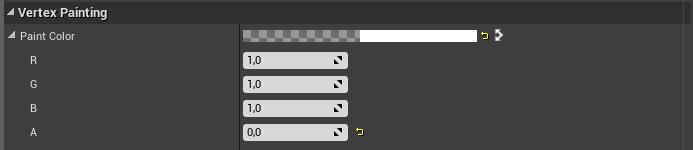
- Reduce the “A” spinner to zero (Figure 39).
Figure 40.
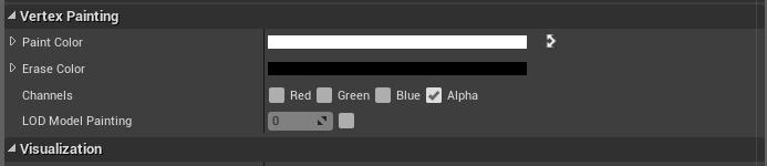
- Uncheck the “Red”, “Green”, and “Blue” check marks and check the “Alpha” checkmark next to “Channels” (Figure 40). You can now erase parts of the decal by painting on it.
Figure 41.
- Reverse the above steps to re-enable the standard painting functionality (Figure 41).
Draw Call Optimization
You can reduce draw calls by using UE4’s built-in merging tool. Follow the steps below to achieve this optimization.
Figure 42.
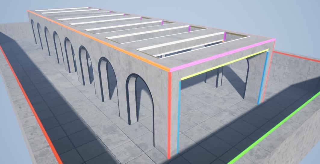
You will merge splines with similar lengths and give each merged set a unique material instance, which will reduce stretching on that particular mesh. The colored edges in figure 1 illustrate how you should only merge edges with similar shapes and lengths (Figure 42).
Figure 43.
- Drag out and position the Edge Bevel Decals (Figure 43).
Figure 44.
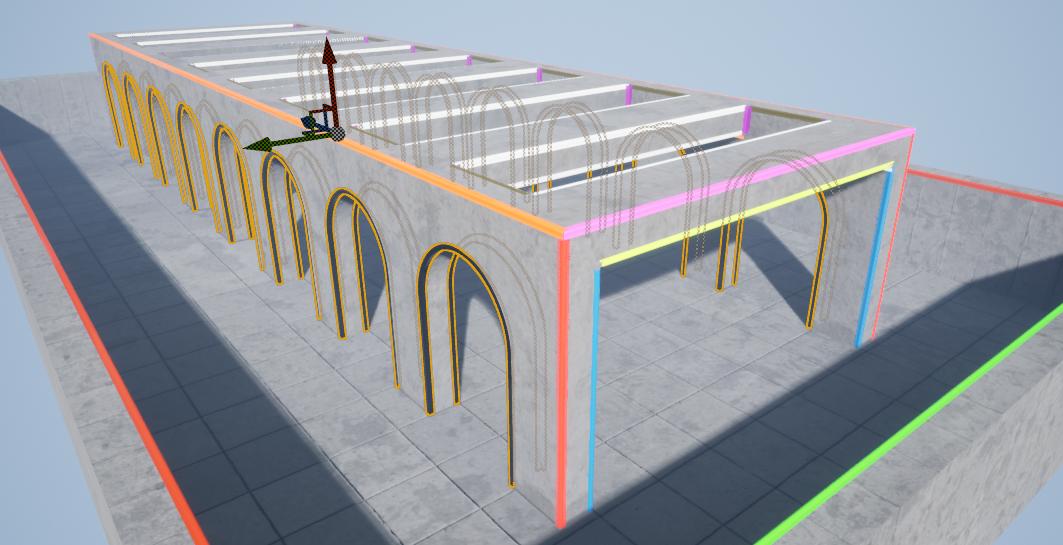
- Select all of the similarly sized decals (Figure 44).
Figure 45.
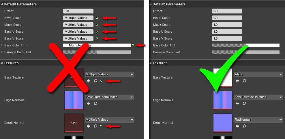
- Make sure you set the parameters on the selected blueprints to their defaults
(Figure 45). Otherwise, the UV’s generated for the merged meshes will be incorrect
(Figure 56). The “Offset” parameter does not affect the merge, so you can leave any changes to it as is.
Figure 46.
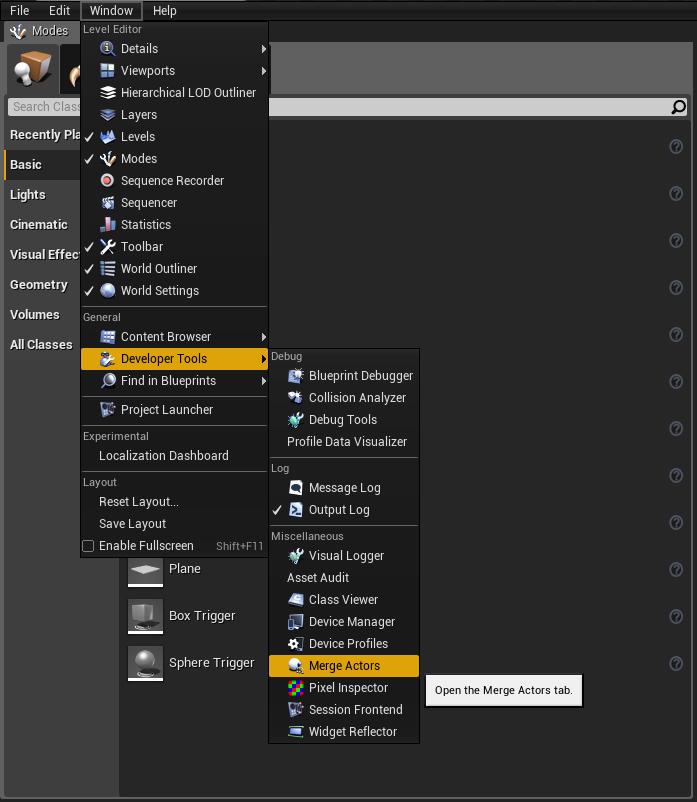
- Go to “Window”, then “Developer Tools”, and finally “Merge Actors” (Figure 46).
Figure 47A.
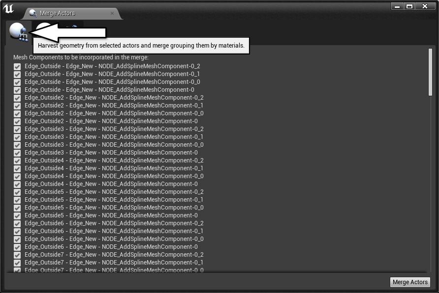
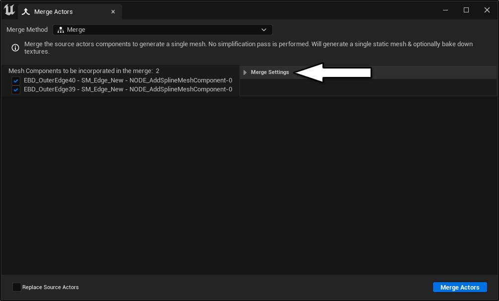
Figure 47B.
- Make sure the “Harvest Geometry” tab is open, which should be the first tab in UE4 (Figure 47A). In UE5, Click on the “Merge Settings” drop-down (Figure 47B).
Figure 48.
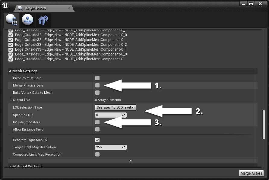
- As shown in Figure 48, you need to uncheck the “Merge Physics Data” checkbox (1) under “Mesh Setting” and click on the “LOD Selection Type” drop-down and select “Use Specific LOD Level” (2). Make sure the “Specific LOD” is zero. Uncheck the “Include Imposters” checkmark (3). You should change the “Target Light Map Resolution” based on the size of the merged mesh.
Figure 49.
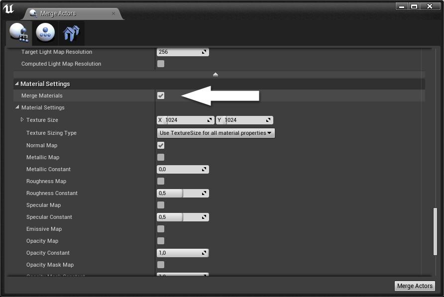
- Under “Material Settings”, enable the “Merge Materials” checkbox (Figure 49).
Figure 50.
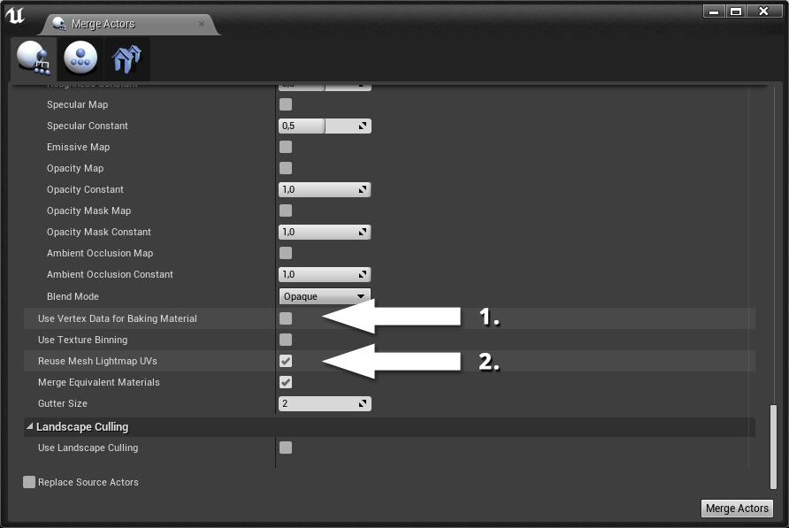
- As shown in Figure 50, scroll down and make sure the “Use Vertex Data for Baking Material” checkbox (1) is disabled and the “Reuse Mesh Lightmap UVs” checkbox (2) is enabled.
Figure 51A.
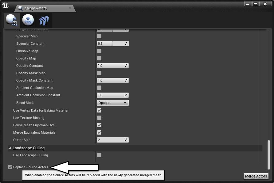
- Enable the “Replace Source Actors” checkbox at the bottom of the window
(Figure 51A).
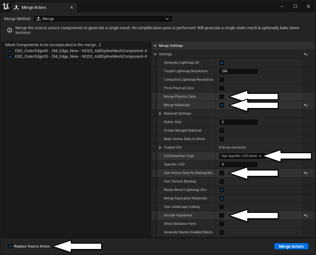
Figure 51B.
- The steps to “Merge Actors” are similar in UE5. Make sure the check-boxes are the same as those shown in (Figure 51B).
Figure 52.
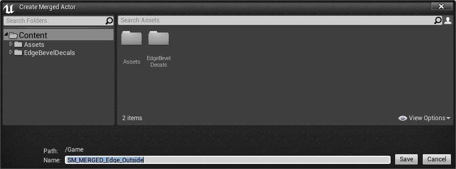
- When you click on “Merge Actors”, a window will open that asks for a location to save the newly merged mesh (Figure 52).
Figure 53.
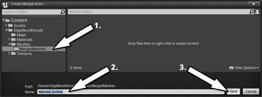
- As shown in Figure 53, choose a folder where you want to save the new mesh (1) and give it an appropriate name (2). Click on the “Save” button when you are happy (3).
Figure 54.
- Check to see if the UV’s of the merged mesh are correct before saving it. Open the merged mesh with the static mesh editor by double-clicking on the mesh file
(Figure 54).
Figure 55.
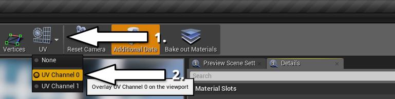
Figure 56.
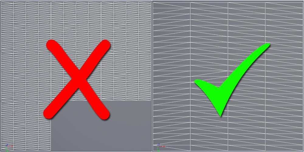
- Click on the UV dropdown button, and then click on the “UV Channel 0” radio button (Figure 55). Figure 56 depicts what “UV Channel 0” should look like.
Figure 57.
Figure 58.
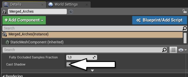
- You need to disable shadow casting on the merged mesh to avoid lighting artifacts (Figure 57). Click on the mesh in the scene. Scroll down to the “Lighting” section and uncheck the “Cast Shadow” checkbox under the “Details” panel
(Figure 58).
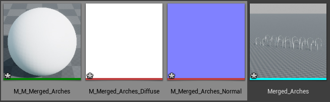
Figure 59.
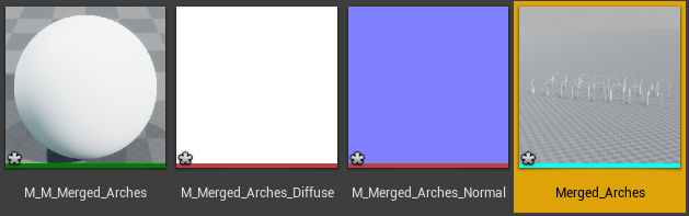
- Back in the folder where you saved the mesh, you need to delete everything other than the mesh file (Figure 59). You need to create a new material instance and apply it to the merged mesh before the editor allows you to delete the other files cleanly.
Figure 60.
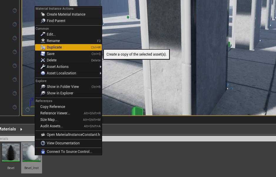
Figure 61.
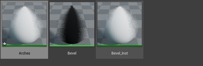
- Go into the materials folder and duplicate the “Bevel_Inst” material instance
(Figure 60). Name this new material instance accordingly and save it (Figure 61).
Figure 62.
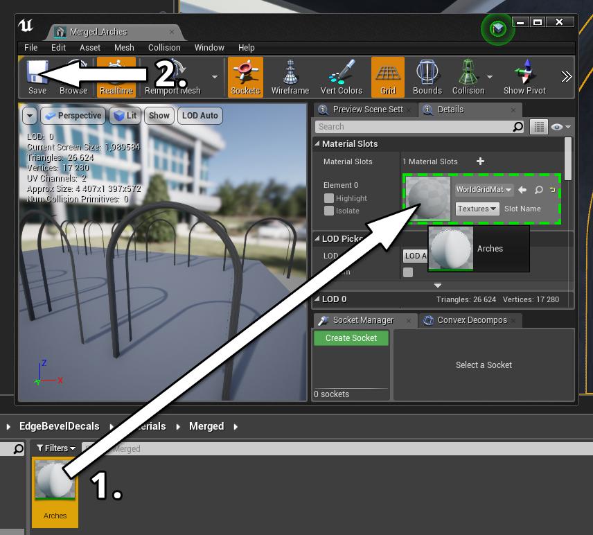
- Double-click on the merged mesh in the content browser (Figure 54) to open the mesh editor. Drag the new material instance [1] into the “Element 0” slot under the “Material Slots” section (Figure 62). Remember to save the mesh after pulling in the new material instance [2].
Figure 63.
- If you want to tweak the material instance, open it alongside the merged mesh to preview the changes (Figure 63). You can also paint damage using the vertex painting tool.
Lighting
Figure 64.
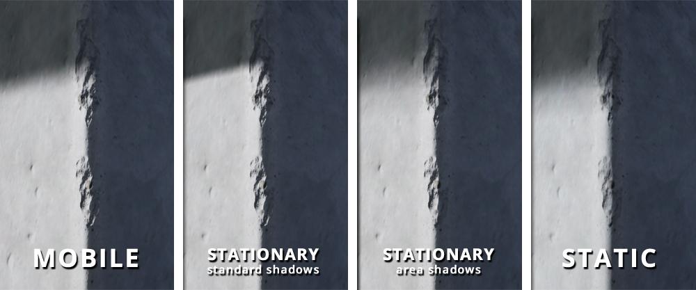
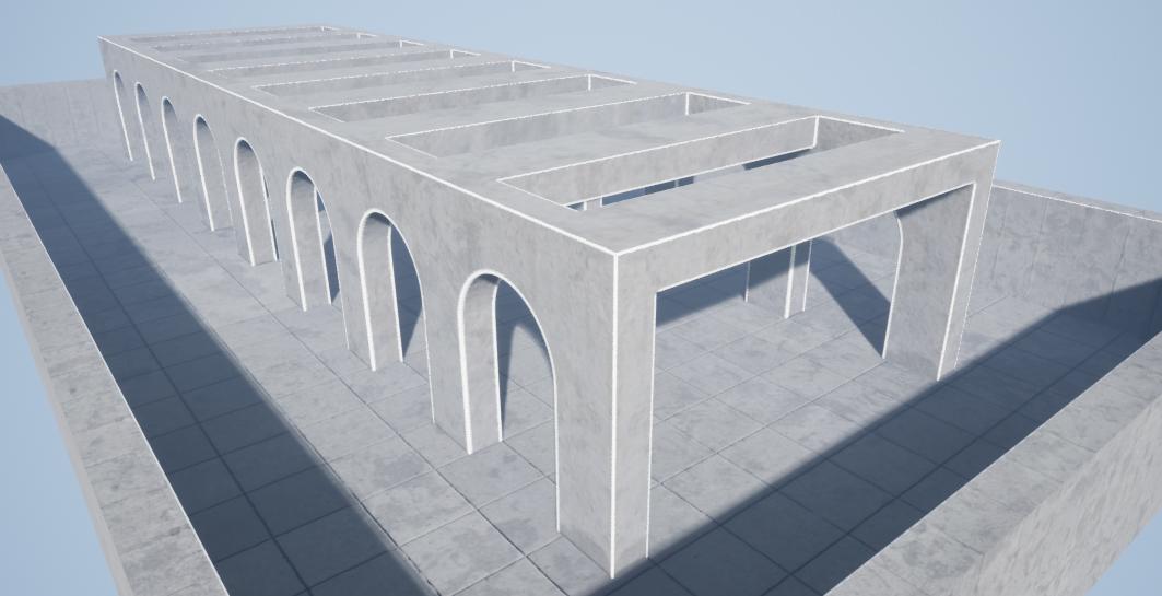
The Edge Bevel Decals work in most lighting conditions (Figure 64). You will, however, need to use either mobile or stationary lights to achieve the best results. Your choice of lighting is crucial when using the vertex painting tool to paint damage.
Try to avoid enabling the area shadows feature when using stationary lights. Otherwise, a minor shadowing artifact could appear where you paint damage.
There is a way that you can increase the quality of the bevel effect when rendering with static lights. Go to “Project Settings”. Under “Engine”, click on “Rendering”, then click on the “Use Normal Maps for Static Lighting” checkbox under the “Lighting” pane.
Fixing Known Issues
Figure 65.
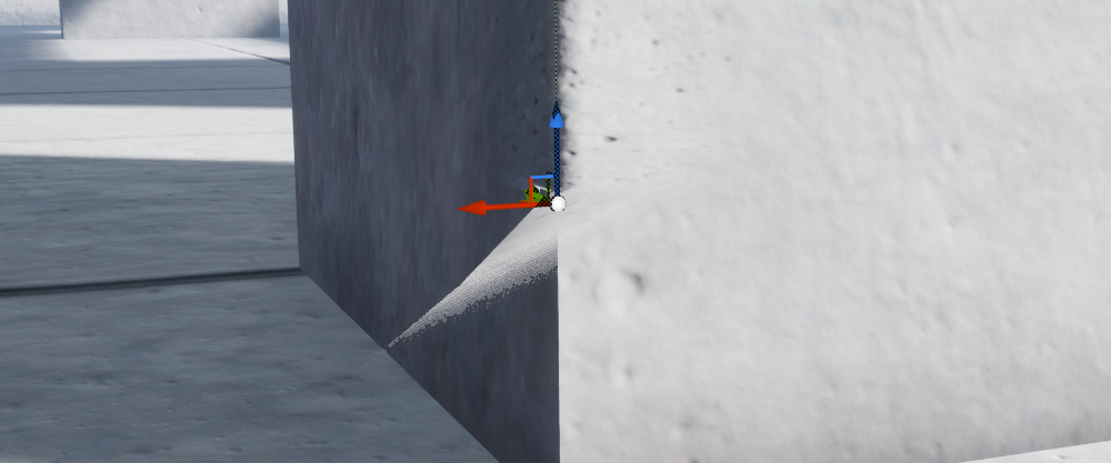
The first known issue appears when the spline extends beyond a certain length
(Figure 65). The mesh will distort near the last spline point.
Figure 66.
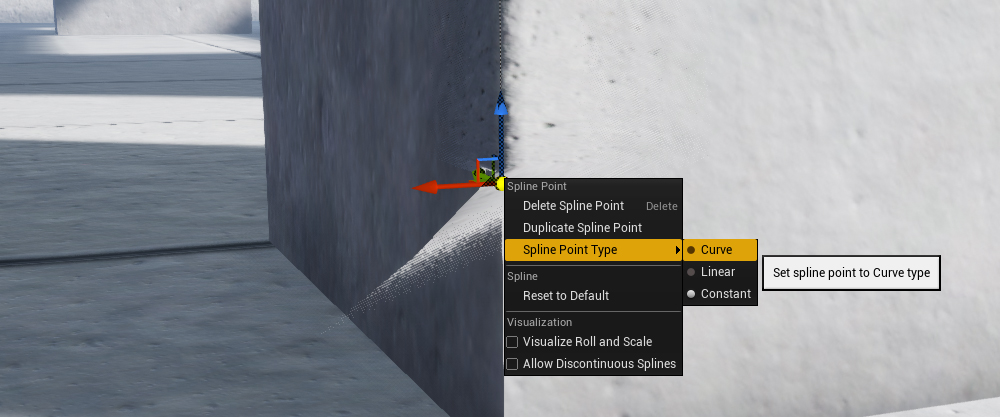
The quickest way to fix the first problem is to set the last spline point to “Curve”
(Figure 66). You can reach the drop-down by right-clicking on the last spline point.
Figure 67.
After setting the spline point to “Curve”, the mesh should be fixed (Figure 67).
Figure 68.
You will experience a similar issue when merging lengthy decals (Figure 68).
Figure 69.
You can fix this issue in one of two ways. The first thing you can try is to erase the problem using the vertex painting tool (Figure 69).
Figure 70.
Alternatively, you can add additional spline points to the decals in question before merging them (Figure 70). The spacing between spline points needs to be the same to ensure that texture tiling is consistent across the spline. The easiest way to achieve a clean merge is to add the requisite amount of points to one of the splines, then duplicate the blueprint.
Figure 71.
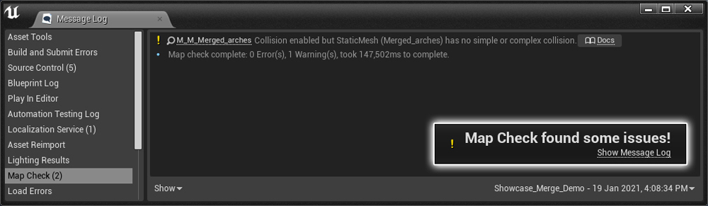
You may encounter a “Map Check” issue when building lighting after merging several decals (Figure 71). The base decal mesh does not have a collision mesh, and is responsible for this issue.
Figure 72.
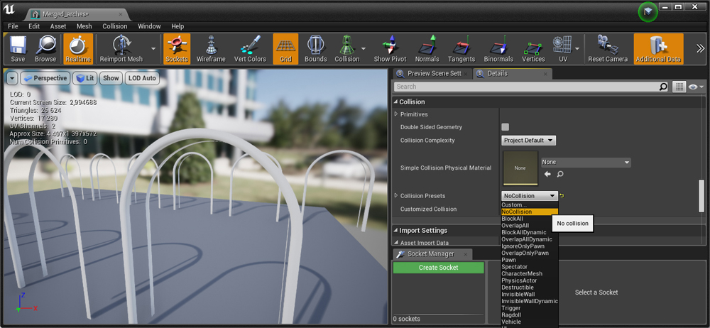
You can fix the “Map Check” error in the static mesh editor. Double-click on the merged decal mesh (Figure 54), scroll down to the “Collision panel” and set the “Collision Presets” drop-down to “NoCollision” (Figure 72). Remember to click the “Save” button in the top left corner of the window to save any changes.
Figure 73.
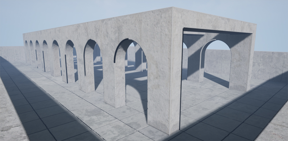
You may encounter a lighting bug when you open the “Showcase_Merged_Edges” map for the first time (Figure 73).
Figure 74.
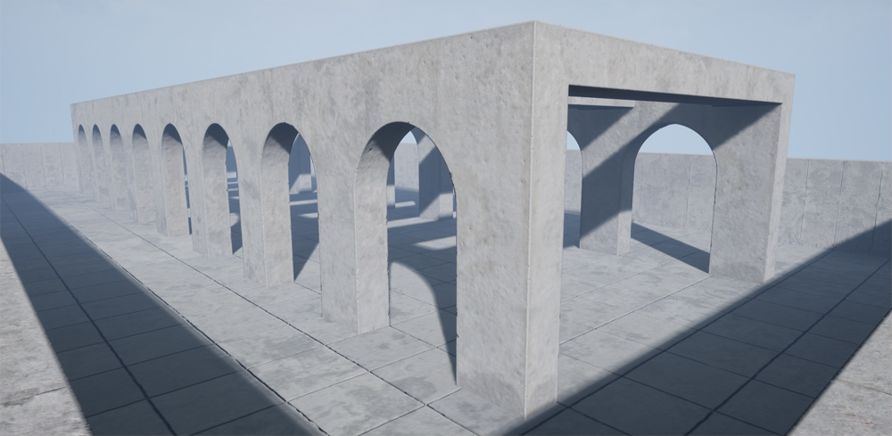
Rebuild the lighting, and the issue should resolve itself (Figure 74). Remember to disable the collision on the merged meshes if you encounter a collision error after the build completes (Figure 72).
Version 2:
Figure 75.
Version 2 of Edge Bevel Decals (Figure 75) adds additional features. The shader simulates damage on a painted edge. The effects include cracked paint, chips, and damage to the substrate. You can use the red, green, and blue vertex painting channels to apply these effects to the edge bevel decal.
Figure 76.
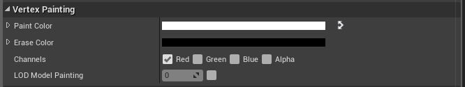
You can use the red channel (Figure 76) to apply cracking paint to the decal.
Figure 77.
The cracked paint channel uses a normal map texture with the “Base Texture” to simulate this effect (Figure 77). The cracks only extend to the boundaries of the decal.
Figure 78.

You can use a custom texture by replacing the “Crack Normal” slot (Figure 78).
Figure 79.

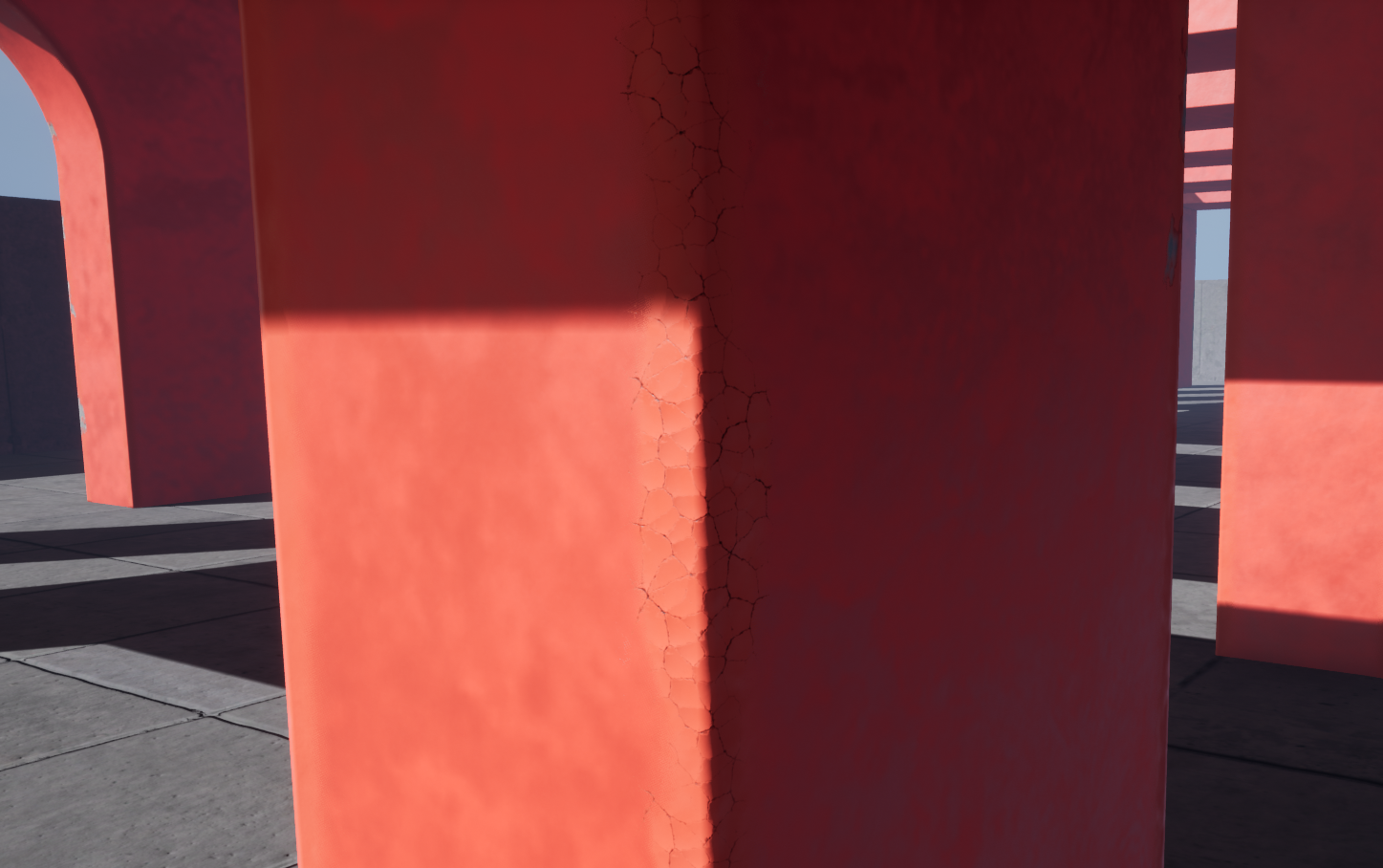
You can apply the chipped paint effect to the decal using the green channel (Figure 79).
Figure 80.
The chipped paint layer reveals the substrate, such as concrete or drywall. You can set the look of this underlying surface by loading a texture into the “damage texture” slot (Figure 80).
Figure 81.

You can specify the normal map texture used by the underlying surface by loading a custom texture into the “Damage Normal” slot (Figure 81).
Figure 82.
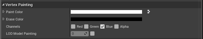
Figure 83.
You can paint the traditional damage effect used in V1 of EBD with the blue channel (Figure 82).
Figure 84.
When you paint the three vertex colors, the material layers damage realistically (Figure 84). The painted channels affect each other in a layered fashion, as they would in real life.
Additional Version 2 Parameters
EBD V2 comes with several parameters that complement the parameters from the first version.
Figure 85.
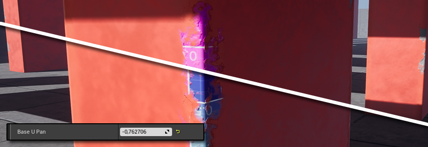
The “Base U Pan” parameter (Figure 85) pans the “Base Texture”, the “Damage Texture” (Figure 18), and the “Damage Normal” on the U axis.
Figure 86.

The “Base V Pan” parameter (Figure 86) pans the “Base Texture”, “Damage Texture” (Figure 18), and the “Damage Normal” on the V axis.
Figure 87.
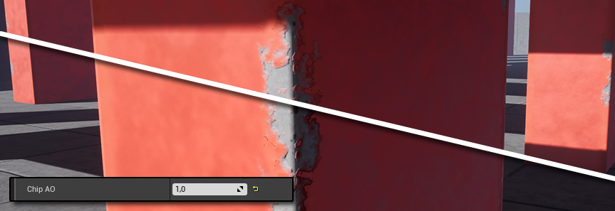
The “Chip AO” parameter (Figure 87) adjusts the strength of the ambient occlusion visible on the edges of the chipped paint.
Figure 88.

You can tweak the edge contrast of the chipped paint layer using the “Chip Contrast” parameter (Figure 88).
Figure 89.
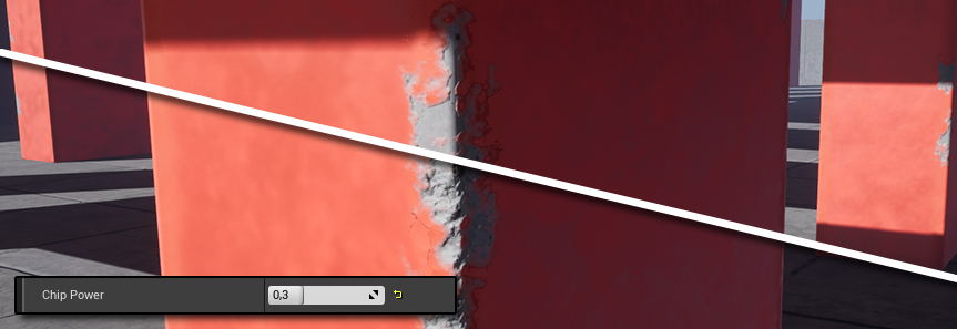
The “Chip Power” parameter (Figure 89) adjusts the depth of the chipped paint layer.
Bonus Blend Shader:
Figure 90.
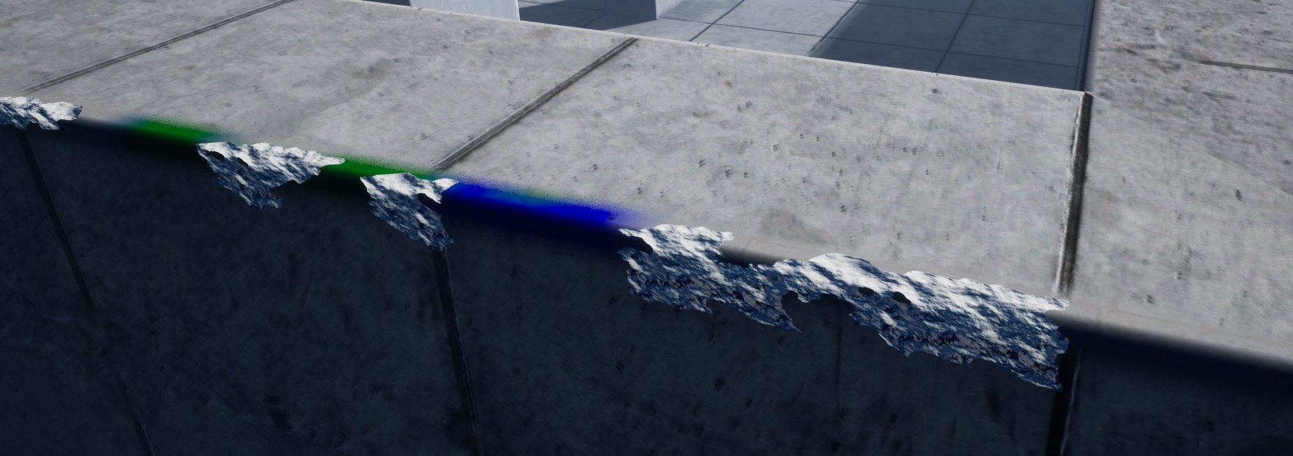
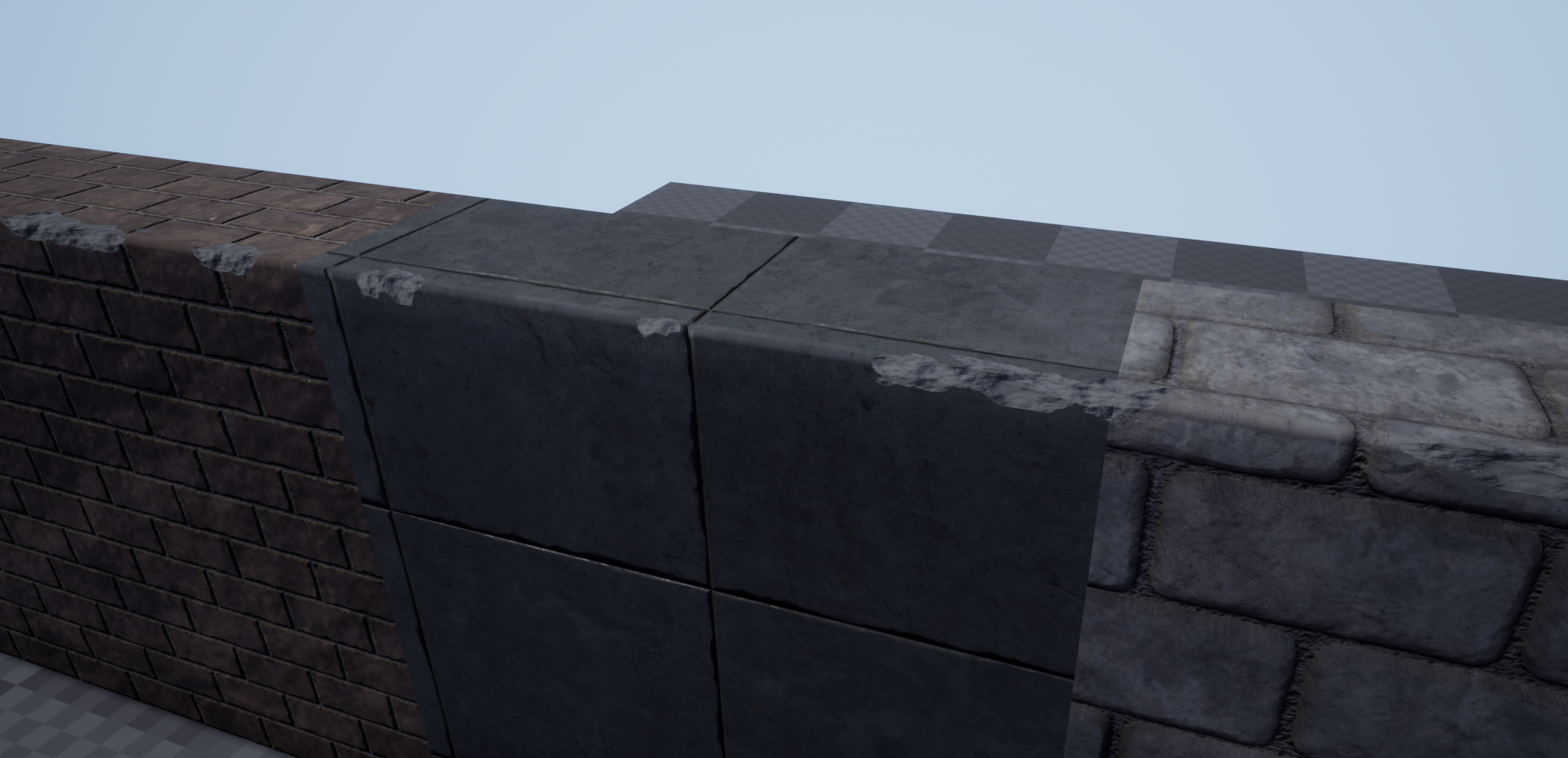
Figure 91.
EBD V2 contains a bonus shader called the “V1_Blend” Shader (Figure 90 & 91). It is an enhanced version 1 shader that allows for blending between up to three different base texture sets. You can now seamlessly match the decal with an underlying mesh that also uses up to three distinct texture sets.
The “V1_Blend” shader’s performance is comparable to the new V2 shader. The shader does not support the layered damage effect available in the new V2 shader, however. The “V1_Blend” shader uses the available vertex channels to paint the three different base textures, the damage effect, and decal opacity.
Figure 92.
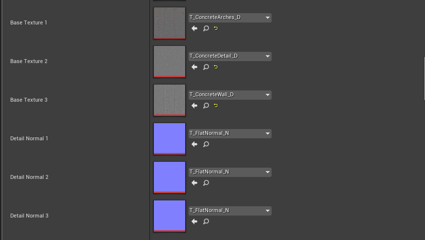
Under the “Textures” roll out you can replace the default “Base Texture” inputs with custom textures (Figure 92). The three “Detail Normal” slots correspond with their respective “Base Texture” counterparts, should you wish to give each “Base Texture” a complimentary normal map. These “Base Texture” sets make use of absolute world space texture coordinates mapped in local space. They will not bend with the shape of spline mesh.

Figure 93.
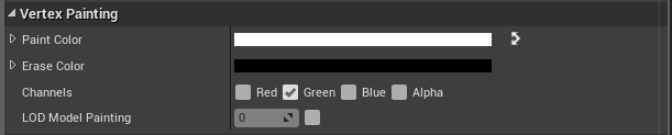
Figure 94.
The first “Base Texture” is visible on the decal by default. You can use the “Red” and “Green” channels to apply the second and third “Base Texture” sets (Figure 93 & 94). You can paint a new base texture by enabling either the “Red” or “Green” channel and painting on the decal while holding the shift key. As soon as you release the shift key, you will be able to erase these sections by painting over them again.
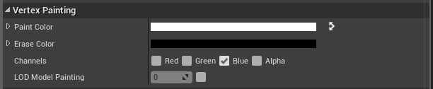
Figure 95.
You can paint edge damage by enabling the “Blue” channel (Figure 95).
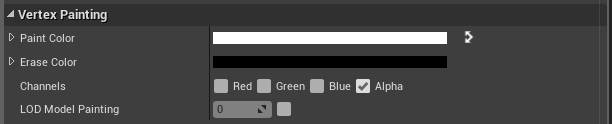
Figure 96.
You can hide parts of the decal using the “Alpha” channel (Figure 96).
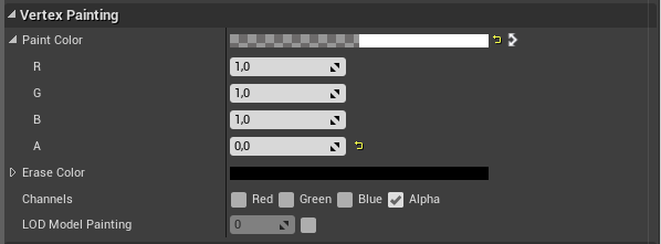
Figure 97.
Make sure you set the “A” value to “0,0” under the “Paint Color” rollout (Figure 97). Paint on the decal to hide the parts you want. You can restore these hidden sections by painting over them while holding down the shift key.
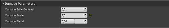
Figure 98.
The “Damage Parameters” (Figure 98) are identical to their V1 counterparts (Figures 22, 23, and 31).
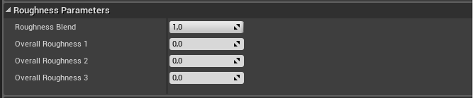
Figure 99.
The “Roughness Parameters” (Figure 99) are also similar to the parameters in the first version. The “Roughness Blend” parameter is identical to the one found in V1 (Figure 26). “Overall Roughness” one through three is similar to the single parameter found in V1 (Figure 32) but affects the three different base texture sets.
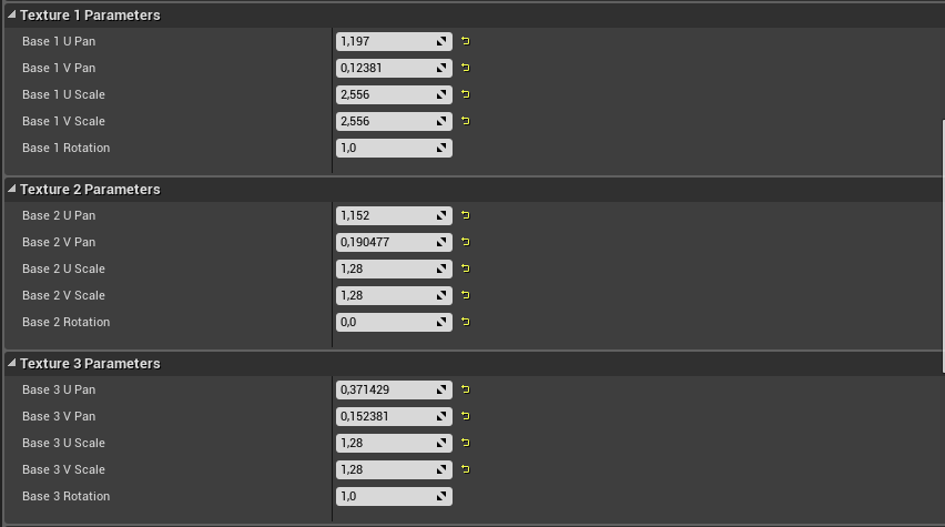
Figure 100.
Independent “Pan”, “Scale”, and “Rotation” controls are now available for all three “Base Texture” sets (Figure 100). When rotating one of the textures, a value of 0.25 equates to 45 degrees of rotation.
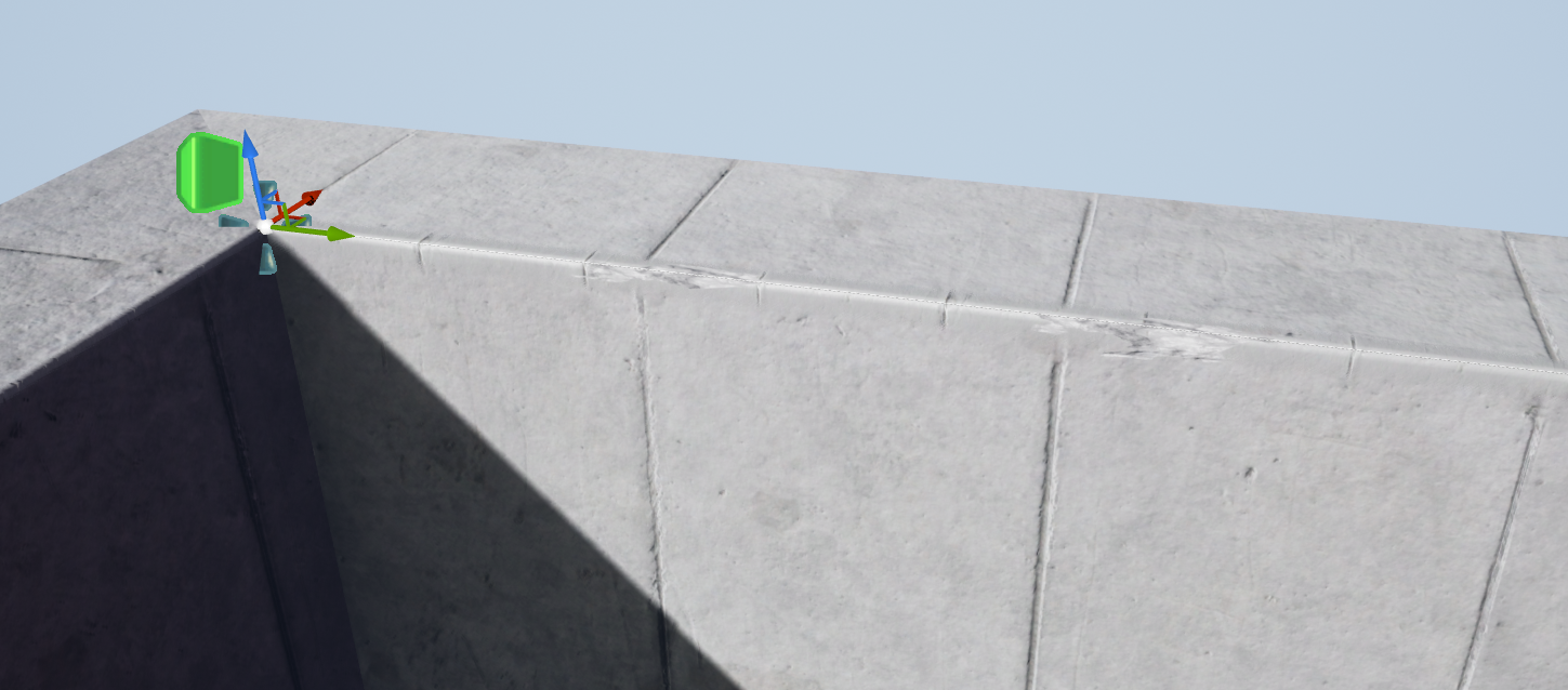
Figure 101.
You have to keep in mind that textures scale from the spline’s origin point when you want to line the decal up with any underlying textures (Figure 101).
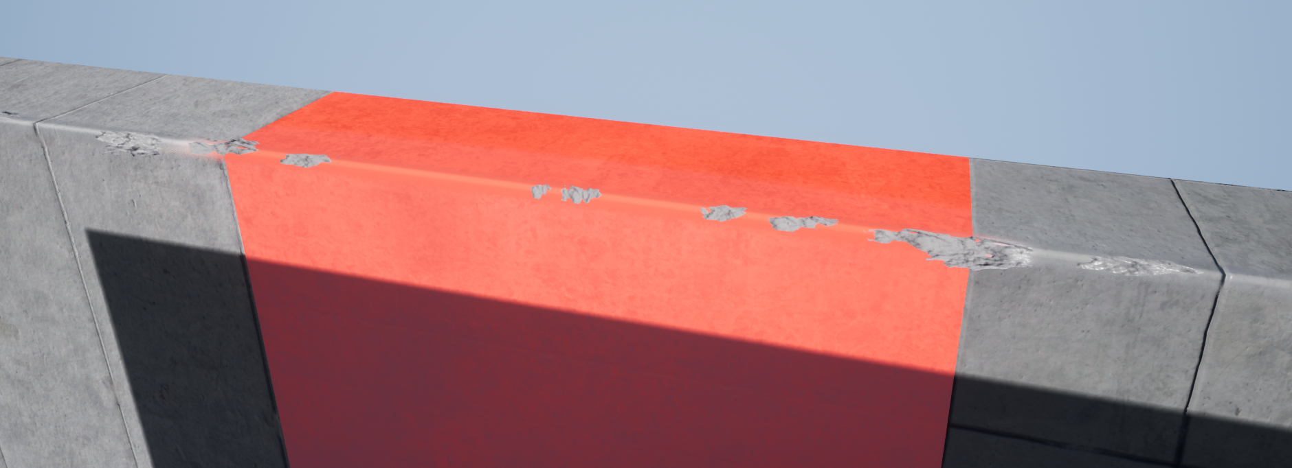
Figure 102.
Sometimes you’ll have an underlying mesh with multiple tiling textures (Figure 102). The new blend shader supports up to three of these textures. You’ll have to apply the underlying textures in a specific order so that it’s easier to align the decal textures with them.
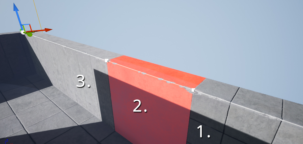
Figure 103.
When you consider the origin point of the decal spline, always apply the tiling textures in the following order on your underlying mesh (Figure 103).
Figure 104.

Figure 105.
Done correctly, the tiling texture furthest to the origin point of the spline will be applied first (Figure 104). It will make aligning the detail textures of the decal exponentially easier (Figure 105) when using the available controls (Figure 100).
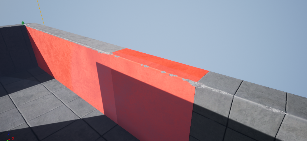
Figure 106.
As soon as you’ve successfully aligned the decal with the furthest most texture, you should follow the same procedure for the second texture (Figure 106).
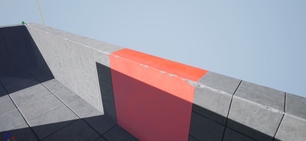
Figure 107.
You need to align the detail texture nearest to the origin point last (Figure 107).
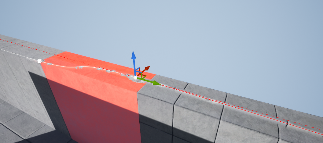
Figure 108.
The detail textures make use of “absolute world position” coordinates so that the spline stretching does not affect texture tiling (Figure 108).
Additional Angles:
The Edge Bevel Decal package now comes with additional angles. You can add decals that are 30°, 45°, 60°, 75°, 120°, and 135°.
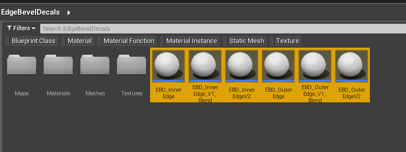
Figure 109.
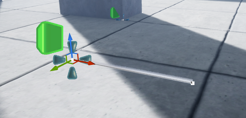
Figure 110.
To add a new angle, drag one of the EBD blueprints (Figure 109) into your scene (Figure 110).
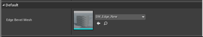
Figure 111.
On the details panel, scroll down to the “Default” roll-out where the “Edge Bevel Mesh” is located (Figure 111).
Figure 112.
In the “Content Browser”, double-click on the “Meshes” folder (Figure 112).
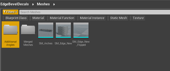
Figure 113.
Double-click on the “AdditionalAngles”, when you are inside the “Meshes” folder (Figure 113).
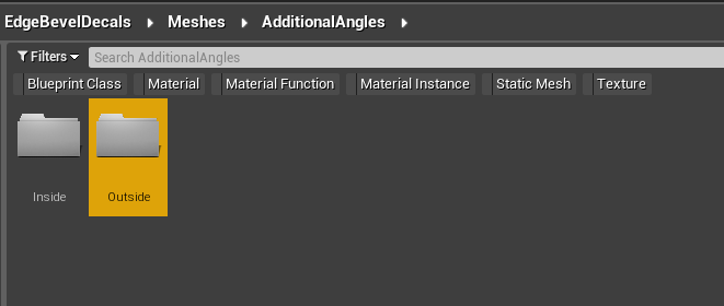
Figure 114.
Double-click on “Inside” or “Outside” when you are inside the “AdditionalAngles” folder. The folder you choose depends on the EBD blueprint you pulled into your scene (Figure 114). Make sure the mesh corresponds to the blueprint you are using. For example, you should use the meshes in the “Outside” folder when you use the “EBD_OuterEdge” blueprint (Figure 112).
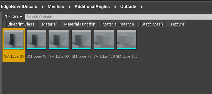
Figure 115.
Inside the folder, you’ll find several angled static mesh edges. Click on the mesh that you want to use. Figure 115 shows the 30° angle selected.
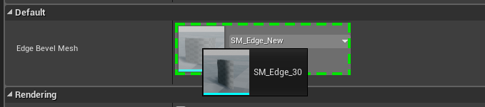
Figure 116.
Click on the EBD blueprint in your scene. Drag the selected static mesh into the “Edge Bevel Mesh” slot in the details panel on the right (Figure 116).
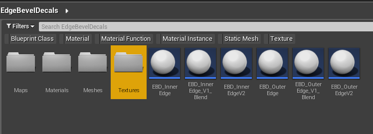
Figure 117.
Each angled mesh has a corresponding bevel texture. Double-click on the “Textures” folder to find them (Figure 117).
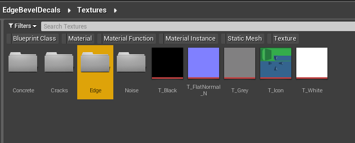
Figure 118.
In the “Textures” folder, double-click on the “Edge” folder (Figure 118).
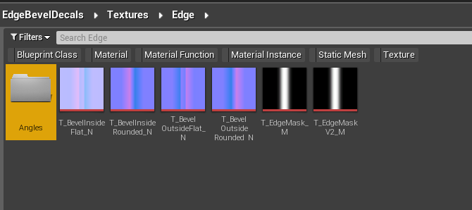
Figure 119.
In the “Edge” folder, double-click the “Angles” folder (Figure 119.
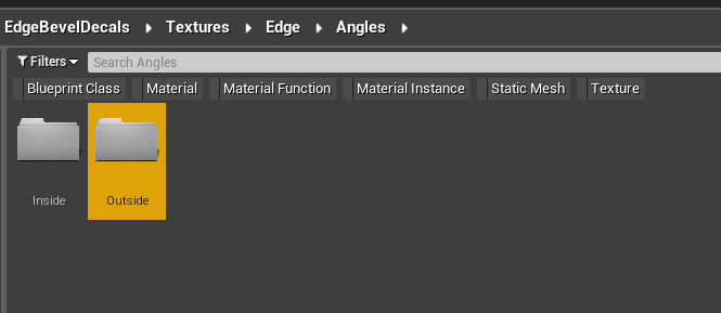
Figure 120.
Double-click on “Inside” or “Outside” when you are inside the “Angles” folder.
The folder you choose depends on the EBD blueprint you pulled into your scene (Figure 120).
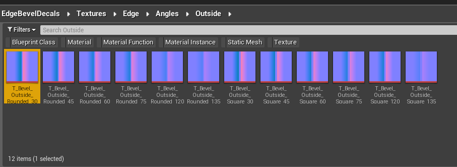
Figure 121.
Inside the folder, you’ll find the bevel textures associated with the edge you pulled into the EBD blueprint. Choose the bevel texture you want to use. Figure 121 shows the “T_Bevel_Outside_Rounded_30” selected.
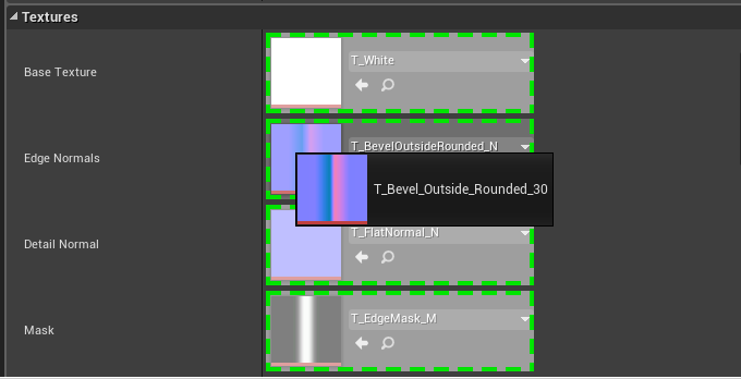
Figure 122.
Click on the EBD blueprint in your scene. Drag the bevel texture into the “Edge Normals” texture slot in the details panel on the right (Figure 122).
Update History
Version 1.0.0 - 27th January 2021
Initial Release
Version 2.0.0 - 27th September 2021
- New layered material
- Bonus V1 material
Version 2.1.0 - 4th January 2023
- Added additional bevel mesh angles.