IMPORTANT - INCORRECT INSTALLATION WILL INVALIDATE WARRANTY
PW-SMB1000 ‘ |

Y O U R I N S T A L L A T I O N I N S T R U C T I O N S
SMARTBOOST - SM(P)
READ ME
This is a high performance, high specification pump and has precise installation requirements.
This booklet provides an overview of the supplied products and is not a substitute for the complete installation instructions supplied with each component. Please pass all manuals on to the householder after installation.
It is necessary to retain proof of purchase in order to facilitate any warranty claim.
Ensure pump has its own or a very good power supply
with recommended 30 mA RCD and suitable type C circuit breaker
QUALIFIED PLUMBER & ELECTRICIAN TO CARRY OUT INSTALLATION
Updated January 2024
WARRANTY
One year from date of purchase (parts and labour) with a second year activated (parts only) on return of the Extended Warranty Form.
Proof of purchase will be required. Note : any labour costs, other than Pump World, will only be covered by prior agreement.
BOX CONTENTS INSTALLATION KIT
Smartboost & Vessel x1 Stainless Steel Flexible 1.0” x2 Y Strainer 1.0” x1
Lever Ball Valve 1.0” x2 Acoustic Mat x1
PUMP PERFORMANCE
MODEL MOTOR DIMENSIONS MAX CLOSED VALVE PRESSURE MAX FLOW
SMARTBOOST 11E 0.75 KW L454 x W200 x H680 MM 7.7 BAR 87 LPM AT 1.4 BAR
SMARTBOOST 12E 1.1 KW L454 x W200 x H680 MM 6.6 BAR 140 LPM AT 1.6 BAR
RECOMMENDED MINIMUM TANK SIZE : 455 LITRE
These pumps are often used to boost the pressure (from a break tank) whilst maintaining a constant pressure during changes in demand. Please seek technical help on 01793 820142 for further information.
KEY POINTS BEFORE PROCEEDING
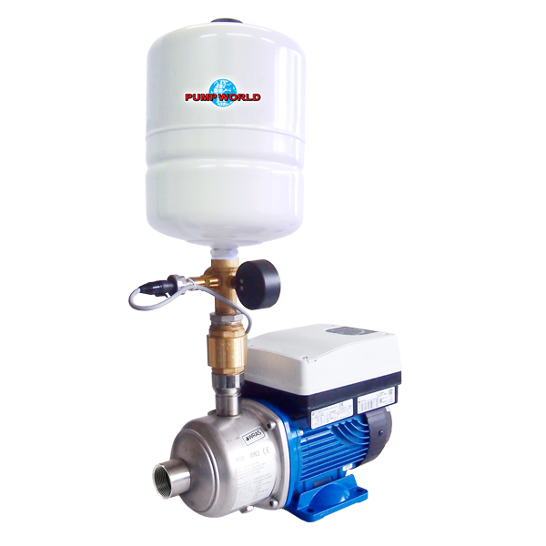
This set consists of a pump, smart inverter and electronic pressure transmitter (also known as the pressure sensor), 5 way connection, vessel and pressure gauge. Always disconnect the inverter from the power supply before carrying out operations on the system’s electrical or mechanical components. After disconnecting from the power source, wait at least 4 minutes before carrying out any work to allow the capacitor in the internal circuit to discharge.
When pumping water from a break tank it is necessary to install a float switch to protect the pump from running dry.
To complete the system, flexible hoses and shut off valves on suction and delivery should be installed.
Electrical Supply Ensure pump has its own or a very good power supply with recommended 30 mA RCD and suitable
type C circuit breaker. Please refer to supplied manufacturer manual for full recommendations.
Water Temperature If pumping, the hot water maximum temperature is 60°C.
Pump Installation The expansion vessel pressure must be set at 0.5 Bar below the pump set point. The vessel must be inflated
and checked when the system and pump is not pressurised. The pump must be adequately ventilated.
Installation Kit Flexibles : Do not bend more than 10 degrees.
Lever Ball Valves : Additional valves should be installed before and after pump to facilitate maintenance.
A ¾” Equilibrium Ball Valve will improve refill of cold storage tank (not supplied).
Jointing compound must not be used in the supply pipework of the pump.
Required By Law All wiring complies with British standards and is fused and earthed (use a 13 amp fuse in spur or plug).
This pump complies with the United Kingdom Water Fitting Byelaws Scheme and must be fitted by a
competent installer in accordance with Water Byelaws and the requirements of the Institute of Electrical Engineers.
EQUIPMENT LAYOUT
We can supply all components listed below, call for specification on 01793 820142
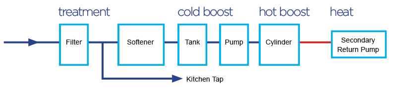
Filter
Water filters improve the taste and quality of your drinking water.
Kitchen Tap
The kitchen tap should be drawn off after the filter and before the rest of the equipment.
Softener
Water softeners collect hard water salts from your water that form limescale - preventing staining and watermarks on sanitary ware and calcium build-up on heating elements, pumps, tanks and vessels.
Tank
Cold water storage to meet demand when required.
Pump
Provides boosted pressure and flow.
Cylinder
Hot water storage to meet demand when required.
Secondary Return Pump
Circulates hot water to provide instant hot water at the taps.
TYPICAL LAYOUTS
SINGLE PUMP LAYOUT

A bypass system, with isolating valve, is recommended to cover loss of pump operation.
TWO PUMP LAYOUT (WITH DUTY ASSIST) FOR UNVENTED SYSTEMS

Note : where a bypass system is installed, it will be necessary to fit a double non-return valve.
BOOSTING GRAVITY / VENTED SYSTEMS - NOT RECOMMENDED
TECHNICAL APPENDIX
- PUMP & CONTROL PANEL
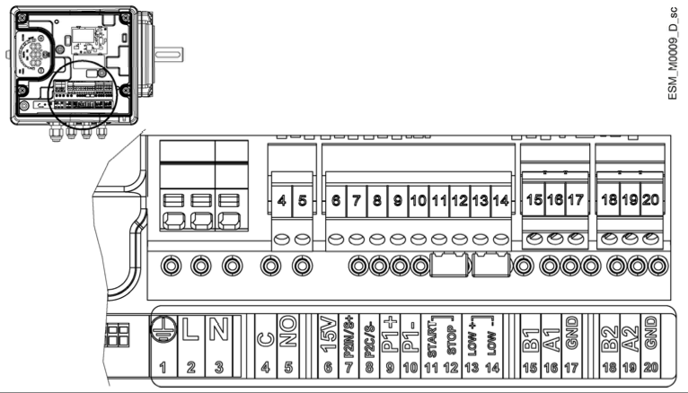
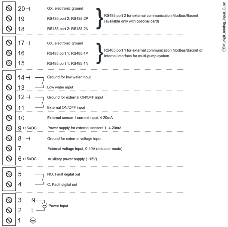
CONTROL PANEL TERMINAL DESCRIPTION
| 12. Ground for External ON / OFF Input with Optional Module with Optional Module |
2. CONTROL PANEL LAYOUT
ALARM CODES
ALARM CODE DESCRIPTION CAUSE
A03 Derating Temperature is too high
A05 Data Memory Low Data memory has corrupted
A06 LOW Alarm Lack of water detection
A15 EEPROM Write Failure
A20 Internal Alarm
A30 Multi-Pump Connection Alarm Multi-pump connection has corrupted
A31 Multi-Pump Comm Lost Multi-pump connection lost
ERROR CODES
ALARM CODE DESCRIPTION CAUSE
E01 Internal Communication Error Internal communication has been lost
E02 Motor Overload Error High motor current
E03 DC-BUS Over-Voltage Error DC-BUS over-voltage
E04 Trip Control Error Motor has stalled
E05 EEPROM Data Memory Error EEPROM data memory has corrupted
E06 Grid Voltage Error Voltage supply out of range
E07 Motor Winding Temperature Error Motor thermal protection trip
E08 Power Module Temperature Error Frequency converter thermal protection trip
E09 Generic Hardware Error Hardware error
E10 Dry Run Error Dry run detection
E11 LOW Error Lack of water detection
E12 Pressure Sensor Error Missing pressure sensor
E14 Low Pressure Error Pressure below minimum threshold
E30 Multi-Pump Error Incompatible multi-pump protocol
Please ensure that once power has been disconnected you allow at least 4 mins for the capacitor to discharge before carrying out any service or repair work.
FLOAT SWITCH OPTIONS | |
* USE TERMINAL 13 AND 14 FOR WIRING * | |
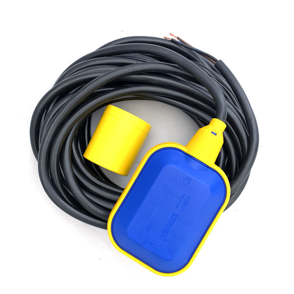
DOUBLE PROTECTION FLOAT Suitable for clean and dirty water. The microswitch assembly inside the float, axially mounted inline with the weight, changes contacts according to the float’s position. Therefore, as the liquid level drops or rises slowly, a pump or flow control suitably connected can be switched in or out to maintain an average level of the liquid. By connecting only one side of the switch, the unit can also be used to fill or empty the tank as required. Float Housing : Non-toxic, corrosion resistant polypropylene. Cable : PVC 3x1, 10.0 m Equipment rated to 50°C. Protection Degree IP68. Use the brown and black wires for low level water protection. The wire that is not used must be correctly insulated. Use terminal 13 and 14 on the pump set for wiring. See control panel layout on page 5. Follow instructions supplied with float switch for full details. | |
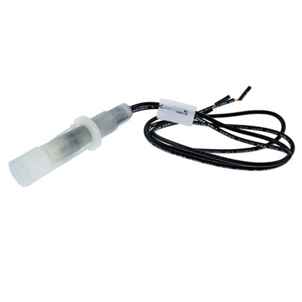
RIGID ARM FLOAT SWITCH WRAS Approved Horizontal mounting float level switch constructed from polypropylene. Consists of reed switch and pivoted actuator magnet. If the cold water tank is undersized, or there is poor mains pressure resulting in poor water recovery, the low level water protection will prevent the pump from running when the water level gets too low in the cold water tank. Use volt free connections. Do not put 230V power on to terminals. | |
TO PURCHASE A FLOAT SWITCH, PLEASE CALL OUR OFFICE ON 01793 820142 | |
TWO PUMP SETS

To link the two pumps together (duty, assist) use a data cable to link terminals 15, 16 and 17 on both pump sets. Two Pump Connection Guide:
Apply the instructions below to both pumps.
Press menu to put in STP (Stop)
Press and hold menu for 3 seconds
Display shows P20
Press menu once
Display shows 000
Use + button to scroll to 66
Press menu
Display shows P21
Scroll to P25
Press Menu
Scroll to NSE (Multiple Pumps)
Press menu
Scroll to P55
Apply the instructions below to pump 1. Apply the instructions below to pump 2 .
Press menu Press menu
Set to 1 Set to 2
Press menu Press menu
Scroll to P56 Scroll to P56
Set to 2 Set to 2
Press Menu Press Menu
To purchase a data cable or for technical advice, please contact us on 01793 820142.
SETTING PRESSURE
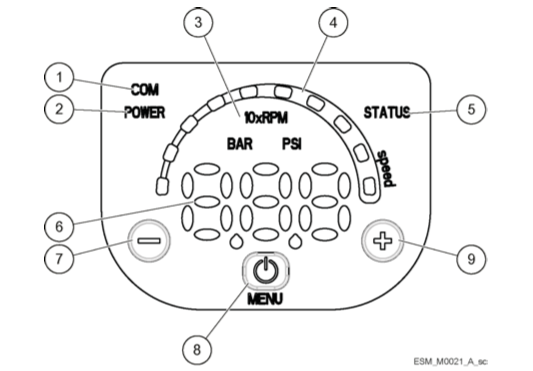
- Communication LED
- Power LED
- Unit of Measure LED
- Speed LED Bar
- Status LED
- Numeric Display
- (-) Minus Button
- Power Button
- (+) Plus Button
The pressure in the vessel must be set 0.5 Bar below the pump setting. Set whilst there is no pressure in the pump system. Note, the vessel pressure must be checked and adjusted annually.
The pump is preset to 4.0 Bar. If required, this can be adjusted by using the - or + buttons. To do this press once the - or + button to show flashing LED display, then use - or + to adjust pressure to required value. When you have reached the required value, leave for a few seconds. Once the solid display returns the new set point has been set.
LEAK DETECTION KIT
(if applicable)
Application : Complete water detection system.
Leak detectors that operate through a water sensitive cable which sounds an alarm and cut the power supply to the pump if a leak is detected.
Supplied with pump sensor cable, alarm and relay. If the sensor cable detects water anywhere along its length, an alarm relay operates to signal that water has been detected, and power to the pump will be shut off. As soon as the leak is fixed and the cable has dried out, the system resets itself. The only requirement is that the water actually touches the sensor cable, high humidity will not cause an alarm unless condensation starts to form.
The leak detectors will detect very small quantities of water, less than 5 ml (one teaspoonful) will trigger an alarm. Response is fast, typically a few seconds.
INSTALLATION
The pump should be mounted horizontally in the centre of a suitable tray with the sensor cable near to, but not touching, the pump. It is advisable to place small weight (not metal) over the cable to keep it flat.
We would recommend fitting an overflow to the tray to allow excess water to drain to the waste.
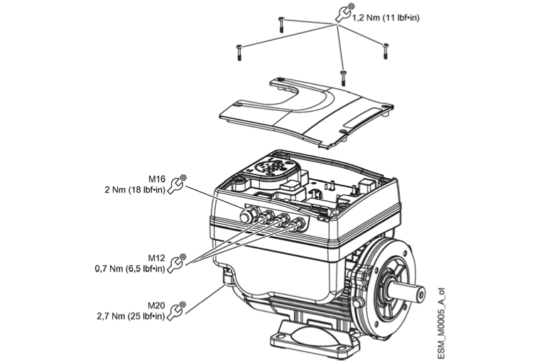
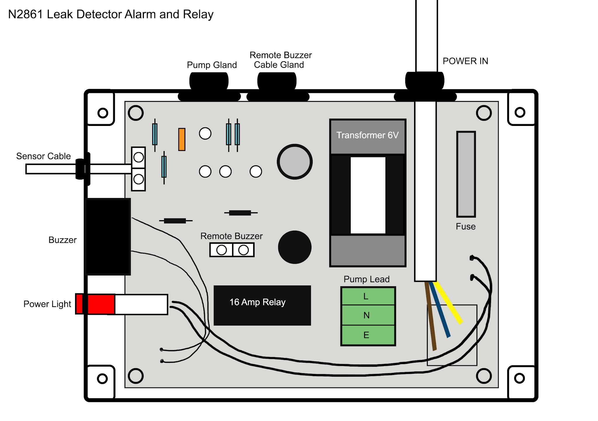
1. Remove the four screws holding the terminal lid cover and wire the pump power lead into the connector block provided (terminals marked ‘Live’, ‘Neutral’ and ‘Earth’). This is located in the green socket on circuit board.
2. Remote alarms can be installed using the volt free connector block also provided.
3. Replace the terminal lid and the four screws.
4. Please note once the alarm has been activated, the pump will not work again until the sensor cable is dry.
If you would like to order the Leak Detection Kit, please call the sales team on 01793 820142.
SMARTBOOST - SMP REGISTRATION FORM
Fill in this form, make a copy and email / post (the copy only) back to us. It is also available to fill in online.
Pump Model | Lot & Works Number (on silver label - by inlet) | |||||
Supplied By (please include name, company name and contact details) | Installed By (please include name, company name and contact details) | |||||
Purchase Date | Install Date | |||||
HOUSEHOLDER DETAILS | ||||||
First Name | Last Name | |||||
Address | ||||||
Post Code | Phone Number | |||||
Email Address | ||||||
INSTALLATION DETAILS | ||||||
Set Pump Pressure | Set Vessel Pressure | |||||
Cold Tank Size | Cold Tank Location | |||||
Pipework Size | Cylinder Recovery Size | |||||
Is a float switch installed? | Is suction dedicated? | |||||
If yes, what type of float switch? | ||||||
WARRANTY
Please complete the form, scan (or photograph) and email it to enquiries@pumpworld.co.uk
You can post a copy of the form to : Pump World, Unit 11 Woodside Road, South Marston Industrial Estate, Swindon, SN3 4WA
Pump World Ltd © All Rights Reserved. Unit 11 Woodside Road South Marston Business Park, Swindon, Wiltshire, SN3 4WA
Tel: 01793 820142 Email : enquiries@pumpworld.co.uk Website : www.pumpworld.co.uk