IMPORTANT - INCORRECT INSTALLATION WILL INVALIDATE WARRANTY
PW-SPR1000 ‘ |

SUPERPRO
READ ME
This is a high performance, high specification pump and has precise installation requirements.
This booklet provides an overview of the supplied products and is not a substitute for the complete installation instructions supplied with each component. Please pass all manuals on to the householder after installation.
It is necessary to retain proof of purchase in order to facilitate any warranty claim.
QUALIFIED PLUMBER & ELECTRICIAN TO CARRY OUT INSTALLATION
Updated December 2023
WARRANTY
One year from date of purchase (parts and labour) with a second year activated (parts only) on return of the Extended Warranty Form.
Proof of purchase will be required. Note : any labour costs, other than Pump World, will only be covered by prior agreement.
BOX CONTENTS INSTALLATION KIT BOX CONTENTS
Superpro Pump x1 Stainless Steel Flexible 1.0” x2
Pressure Switch Control x1 Lever Ball Valve 1.0” x2
Acoustic Mat x1 Y Strainer 1.0” x1
PUMP PERFORMANCE
MODEL KW DIMENSIONS (MM) MAX PRESSURE MAX FLOW RATE
SUPERPRO 3E 0.45 L336 x W155 x H349 3.5 BAR 70 LPM
SUPERPRO 4E 0.55 L356 x W155 x H349 4.6 BAR 70 LPM
SUPERPRO 5A 0.75 L390 x W155 x H349 5.8 BAR 70 LPM
SUPERPRO 6A 0.95 L450 x W155 x H349 6.0 BAR 120 LPM
COMBI BOILER INSTALLATION : RECOMMENDED MINIMUM COLD WATER TANK SIZE : 225 LITRE
UNVENTED CYLINDER INSTALLATION : RECOMMENDED MINIMUM COLD WATER TANK SIZE : 450 LITRE
These pumps are often used to boost the pressure for the whole house when one pump is used to pump the hot water and the other to cold. These instructions are for a system where each pump is controlled by a pressure switch which enables them to be used (automatically) in a negative head situation. These pumps can be sited independently. This pump is not suitable for pumping toilets. Please seek technical help on 01793 820142 for further information.
KEY POINTS BEFORE PROCEEDING
Cylinder Connection Use an Essex flange or similar. Do not use a Surrey or Warix flange, or vent connection.
Water Temperature The hot water temperature at the pump should not exceed 60°C.
Gas boiler 2 - 3 or 80°C (to ensure temperature at the hot pump does not exceed 60°C).
If a cylinder thermostat is not fitted, a temperature regulator must be used. If both a cylinder thermostat and
regulator are used, the cylinder thermostat must be a minimum of 65°C.
Pipework 28 mm pipework must be used to and from the pump.
32 mm pipework must be used for the recovery supply to the cylinder.
Both hot and cold supplies must be totally dedicated - no draw offs before the pump.
Pump Location Hot Pump : On the floor, adjacent to the cylinder (not above the cylinder).
Cold Pump : Pump and pipework must be below the storage tank.
Pumps must be placed (on the acoustic mat) on a flat surface ie. paving slab on concrete floor is preferred.
Cold Water Storage We recommend double the cold water capacity to that of the hot water cylinder.
The pump must not be connected directly to the mains water supply.
Pump Installation The pump must be flooded before connecting outlet pipework by attaching tube to outlets, opening inlet
isolating valves and allowing water to flow through the pump (power off) into a container.
The pump must be adequately ventilated.
Installation Kit Flexibles : Do not bend more than 10 degrees.
Lever Ball Valves : Additional valves should be installed before and after pump to facilitate maintenance.
Not installing the supplied kit may invalidate your warranty.
A ¾” Equilibrium Ball Valve will improve refill of cold storage tank (not supplied).
Jointing compound must not be used in the supply pipework of the pump.
Required By Law All wiring complies with British standards and is fused and earthed (use a 13 amp fuse in spur or plug).
This pump must be fitted by a competent installer in accordance with Water Bylaws and the requirements of
the Institute of Electrical Engineers.
EQUIPMENT LAYOUT
We can supply all components listed below, call for specification on 01793 820142
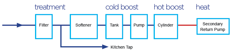
Filter
Water filters improve the taste and quality of your drinking water.
Kitchen Tap
The kitchen tap should be drawn off after the filter and before the rest of the equipment.
Softener
Water softeners collect hard water salts from your water that form limescale - preventing staining and watermarks on sanitary ware and calcium build-up on heating elements, pumps, tanks and vessels.
Tank
Cold water storage to meet demand when required.
Pump
Provides boosted pressure and flow.
Cylinder
Hot water storage to meet demand when required.
Secondary Return Pump
Circulates hot water to provide instant hot water at the taps.
TYPICAL LAYOUTS

Note : where a bypass system is installed, it will be necessary to fit a double non-return valve.

CYLINDER FITTINGS
✔ | X | X |
Essex Flange | Surrey Flange | Off Vent |
HOT WATER TEMPERATURE
The temperature at the pump should not exceed 60’C.
If a cylinder thermostat is not fitted, a temperature regulator must be used.
If both a cylinder thermostat and regulator are used, the cylinder thermostat must be a minimum of 65°C.
NOISE
These are quiet pumps and the following recommendations are made to minimise any extraneous noises.
- Pump should be placed on the acoustic mat provided to help absorb vibration.
- Pump must not be screwed or bolted to the floor.
- Pump is recommended for placing on a paving slab or concrete floor.
- Ensure that all pipework is firmly secured and not in contact with any stud walls.
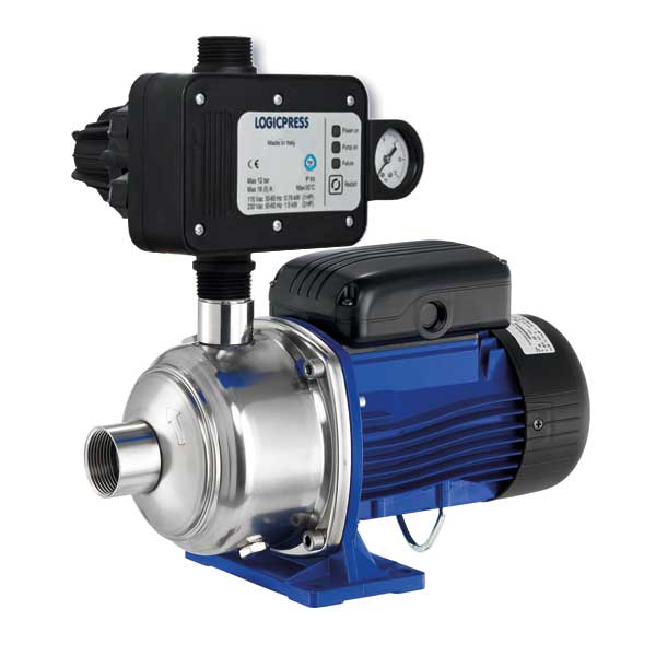
LOGICPRESS PRESSURE SWITCH
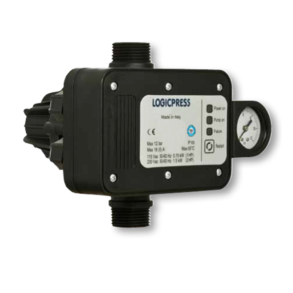
Application : A device for the control and protection of the electric pump.
Starts and stops the pump depending on the opening and closing of the taps. Stops the pump in case of a water shortage and protects it against dry running. The Logicpress can be energised with either 115 Vac or 230 Vac. Equipped with automatic restart in case of failure and anti-jamming function. The Logicpress can be installed on surface or submerged pumps. Maintenance free.
INSTALLATION & START UP
The device can be installed directly on the pump or between the pump and the first tap.
To wire the Power Supply | L : Live | N : Neutral | E : Earth | To wire the Pump Motor | U : Live | V : Neutral | E : Earth |
Make all the electrical connections, check that the pump is correctly primed, open a tap and energise.
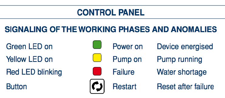
The green ‘power on’ LED will light up on the control panel and the pump will start (yellow ‘pump on’ LED lit up) and will keep running for several seconds to start up the system. If this time is insufficient, the device will stop the pump (red failure LED). Keep the restart button pushed in until the red failure LED turns off and the water comes out of the opened tap. When the tap is closed the pump will stop after a few seconds (yellow ‘pump on’ LED turns off). From now on the device will turn the pump on and off depending on the opening and closing of the tap. In case of water shortage the device will stop the pump and protect against dry running (red failure LED).
AUTOMATIC RESTART & ANTI-JAMMING FUNCTION
In case of stopping due to water shortage, the device will automatically make 10 double attempts to rearm over the 24 hours following the failure, each lasting approximately 5 seconds to allow the pump and the system to reload if possible. After the last failed rearming attempt, the device will remain permanently in alarm (red failure LED blinking) pending manual rearming by pressing the restart button. The user can try to rearm the device at any time by pressing the restart button. If for any reason the pump remains idle for 24 consecutive hours, the device will carry out a start up of the pump motor for about 5 seconds. In case of a temporary blackout, the device will automatically rearm once electricity returns.
Maximum Pressure 12.0 Bar Maximum Temperature 65°C Motor Rating 16 (8) amps, 0.75 - 1.50 kw Connection Size 1.0” BSP M Protection Degree IP65 |
CONTROLLER FAULT FINDER
Pump Does Not Stop This could be caused by :
1. System loss greater than the minimum flow.
2. Water losses over 0.5 lpm - check installation, taps etc for leaks.
3. Insufficient control pump pressure - check pressure gauge (minimum 1.5 Bar)
4. Air in pump - pressure gauge will read low or oscillating reading.
5. Electrical problem - check wiring against instructions.
Check procedure :
1. Run the pump, then close isolating valve after pump. If pump stops it indicates
that the problem is loss of pressure after pump and controller ie. leaking pipework or dripping tap.
2. If the pump continues running with this isolating valve closed, re-open the valve and then close the isolating valve before the pump. If the pump stops it indicates pressure loss is back through the controller. This is normally due to the non-return valve letting by either because of debris on the seating or a damaged non-return valve. This may require the controller to be changed.
Pump Does Not Start This could be caused by :
1. No water supply.
2. Electrical supply problem / blown fuse.
Check procedure :
1. Check water supply by restarting the pump by the red reset switch.
2. Check electrical wiring against instructions. Check fuse (13 amp).
Pump Starts & Stops This could be caused by :
1. System loss less than the minimum flow.
2. Small loss of water in system - less than 0.5 lpm.
3. Air in system.
Check procedure :
1. Check for leaks, dripping taps, valves etc.
2. If you suspect air is in the system, please see Air Faults on page 7.
Other The pump starts but fails to restart - the water column is too high.
The pump jams - suction difficulties / actual pump prevalence is insufficient.
The controller may require resetting - press ‘reset’ and hold for 30 seconds.
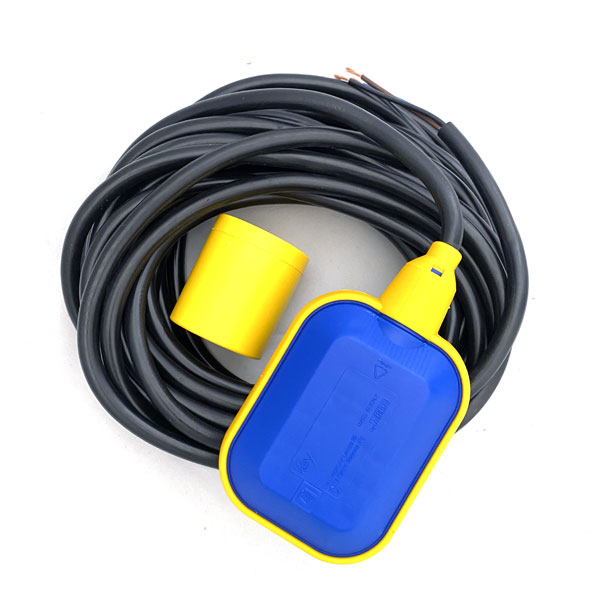
FLOAT SWITCH OPTIONS (IF APPLICABLE)
DOUBLE PROTECTION FLOAT KIT Suitable for clean and grey water. The microswitch assembly inside the float, axially mounted inline with the weight, changes contacts according to the float’s position. Therefore, as the liquid level drops or rises slowly, a pump or flow control suitably connected can be switched in or out to maintain an average level of the liquid. By connecting only one side of the switch, the unit can also be used to fill or empty the tank as required. Float Housing : Non-toxic, corrosion resistant polypropylene. Cable : PVC 3x1, 10.0 m Equipment rated to 50°C. Protection Degree IP68. Use the brown and black wires on the float switch for low level water protection. The wire that is not used must be correctly insulated. Follow instructions supplied with float switch and control box for installation. RIGID ARM FLOAT SWITCH KIT Horizontal mounting float level switch constructed from polypropylene. Consists of reed switch and pivoted actuator magnet. If the cold water tank is undersized, or there is poor mains pressure resulting in poor water recovery, the low level water protection will prevent the pump from running when the water level gets too low in the cold water tank. Use volt free connections. Do not put 230V power on to terminals. Follow instructions supplied with float and control box for installation. If you would like to order a float switch kit, please call the sales team on 01793 820142. |
SUPERPRO FAULT FINDER / AIR FAULTS
No Flow of Water This could be caused by :
1. Pressure switch may be faulty - contact us for recommendations.
2. Blocked filters in inlet hose, mixing valve or shower head - check and clean.
3. Air in system - see end of page.
Pump Switches On / Off This could be caused by :
Independently (Hunting) 1. Back pressure / ‘hammer blow’ - check that Essex flange is used and that both
hot and cold supplies to pump are dedicated.
2. Leaks in system - check pipework and pump.
3. Restrictions in system - check for high restriction in system (toilet).
4. Air in system - see end of page.
Pump Switches Off This could be caused by :
Independently 1. Electrical failure - check electrics.
2. Pump overheated / thermal overload - if pump body hot, leave to cool then try.
Continuous Running This could be caused by :
When Shower Is Off 1. Air trapped in flow switch - see end of page.
Noisy Pump This could be caused by :
1. Cavitation, air in system - see end of page.
2. Bearings - usually after long term use and from air or water starvation.
Pressure / Temperature This could be caused by :
Variation 1. Air or water starvation - see end of page.
AIR FAULTS
- Water too hot (above mid 60°C) - check cylinder thermostat is set at 55°C. If there is no thermostat, a temperature regulator should be fitted.
- Wrong cylinder fitting - check that an Essex flange has been used.
- Run out of water (short period) - check that the cold water tank is refilling fast enough to maintain a level above the outlet. A ¾” Equilibrium Ball Valve will improve the refill into the cold storage tank. Also for the larger pumps, check the pipe size from the cold tank to the cylinder (28 mm recommended) A Double Protection Float Switch Kit will protect the pump by turning it off if the water level falls too low
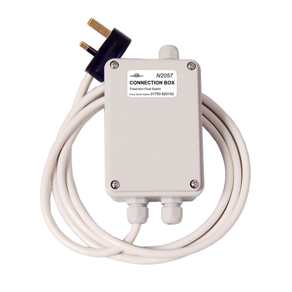
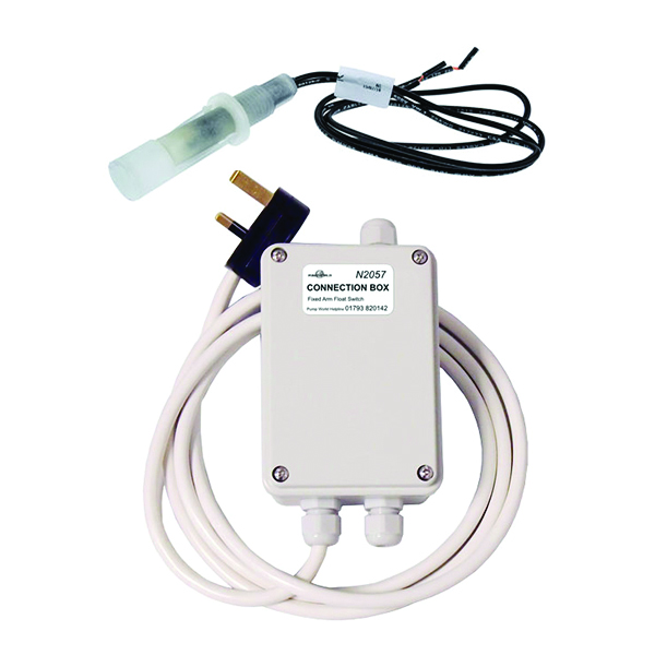
LEAK DETECTION KIT
(if applicable)
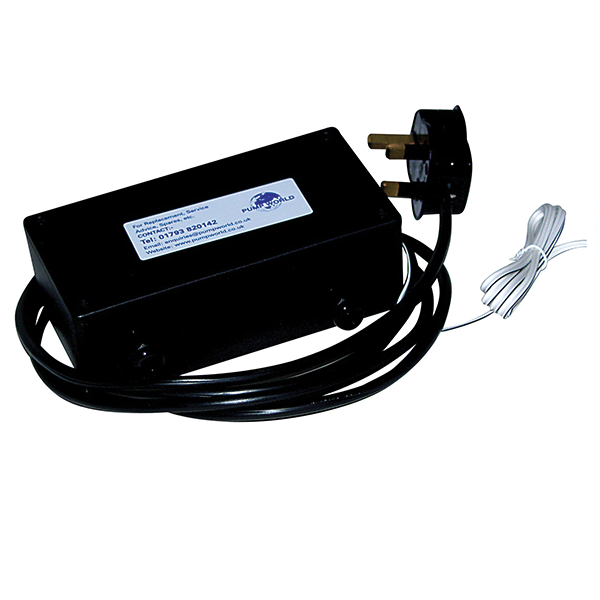
Application : Complete water detection system.
Leak detectors that operate through a water sensitive cable which sounds an alarm and cut the power supply to the pump if a leak is detected.
Supplied with pump sensor cable, alarm and relay. If the sensor cable detects water anywhere along its length, an alarm relay operates to signal that water has been detected, and power to the pump will be shut off. As soon as the leak is fixed and the cable has dried out, the system resets itself. The only requirement is that the water actually touches the sensor cable, high humidity will not cause an alarm unless condensation starts to form.

The leak detectors will detect very small quantities of water, less than 5 ml (one teaspoonful) will trigger an alarm. Response is fast, typically a few seconds.
INSTALLATION
The pump should be mounted horizontally in the centre of a suitable tray with the sensor cable near to, but not touching, the pump. It is advisable to place small weight (not metal) over the cable to keep it flat.
We would recommend fitting an overflow to the tray to allow excess water to drain to the waste.
1. Remove the four screws holding the terminal lid cover and wire the pump power lead into the connector block provided (terminals marked ‘Live’, ‘Neutral’ and ‘Earth’). This is located in the green socket on circuit board.
2. Remote alarms can be installed using the volt free connector block also provided.
3. Replace the terminal lid and the four screws.
4. Please note once the alarm has been activated, the pump will not work again until the sensor cable is dry.
If you would like to order the Leak Detection Kit, please call the sales team on 01793 820142.
REGISTER YOUR PUMP INSTALLATION
Fill in this form, make a copy and email / post (the copy only) back to us. It is also available to fill in online.
Pump Model | Lot & Works Number (on silver label - by inlet) | |||||
Supplied By (please include name, company name and contact details) | Installed By (please include name, company name and contact details) | |||||
Purchase Date | Install Date | |||||
HOUSEHOLDER DETAILS | ||||||
First Name | Last Name | |||||
Address | ||||||
Post Code | Phone Number | |||||
Email Address | ||||||
INSTALLATION DETAILS | ||||||
Set Pump Pressure | Set Vessel Pressure | |||||
Cold Tank Size | Cold Tank Location | |||||
Pipework Size | Cylinder Recovery Size | |||||
Is a float switch installed? | Is suction dedicated? | |||||
If yes, what type of float switch? | ||||||
WARRANTY
Please complete the form, scan (or photograph) and email it to enquiries@pumpworld.co.uk
You can post a copy of the form to : Pump World, Unit 11 Woodside Road, South Marston Industrial Estate, Swindon, SN3 4WA
You can fill the form in online via our website - Service > Register My Pump
Pump World Ltd © All Rights Reserved. Unit 11 Woodside Road South Marston Business Park, Swindon, Wiltshire, SN3 4WA
Tel: 01793 820142 Email : enquiries@pumpworld.co.uk Website : www.pumpworld.co.uk